Warpverter
A Serious Electronic Project For The Expert DIYer
The WG (Wiseguy) Inverter
This page is a work in progress. Keep checking back as it fills out ... or if you have any questions or suggestions ... email [email protected]
If the idea of building a Warpverter and having to source and wind four separate toroids is a little daunting ... an alternative may be to build a WG or Wiseguy Inverter.
Read on to learn the background of this exciting redevelopment of the OzInverter ... the home built inverter that began the DIY inverter trend all those years ago.
There is enough information on this and associated pages, along with circuits, files and guides ... to build a WG Inverter capable of supplying a constant 6kW ... and even information on how to double up the power board and toroid ... to build a 12kW version.
This guide is based on many of Wiseguy’s posts from the Back Shed forum … along with more from KeepIS and Poida, other key contributors to the project.
Wiseguy has been on the scene in the back shed for many years and as an Electronic Engineer had been involved in trying to determine why some Ozinverters would work perfectly and yet others would randomly blow up for no obvious reason.
His analysis of the design and experimenting led to a number of changes that improved the reliability considerably … and eventually led to a complete new layout altogether … now called a Wiseguy or WG Inverter.
A further improvement has been the development of a control board powered by an Arduino Nano, along with a 20 character by 4 line display.
Having a smart controller has allowed integrating a soft start system where the main filter capacitors are automatically pre-charged before the inverter is allowed to start ... and also auto shut down in event of overcurrent and low battery voltage etc.
The display shows ...
Vin … DC Voltage In … battery voltage
Vcap … Voltage across Capacitor bank
VAC … Voltage AC … AC voltage out
AAC … Amps AC … AC amps out
Temperature … of the toroid and the heatsink
Indicates if either fans are running
% of PWM power drive 0.0 - 99.9%
Error/fault codes
With this controller you can run the inverter as a 24V, 36V or 48V inverter ... with essentially no changes to the electronics.
The Toroid and the choke are the only parts that need to be changed to suit the DC input voltage and power output requirement.
KeepIS has built several versions of the Wiseguy inverter, all documented over on the Back Shed … effectively proving Wiseguy’s work and providing constant feedback on real life use (and abuse :)).
He also has massive electronics and project building skills … and is a prolific experimenter … constantly exploring the limits to test every new segment of the design and method of building.
Read why KeepIS decided to go down the “Wiseguy” track …
“Way back, I actually purchased two other boards for an inverter build.
Once I got hold of the Wiseguy board and design, there was just no contest in it for the size, quality, stability and relative simplicity of building Wiseguys design and power board.
IMHO, in combination with the New Nano R6 controller, it's simply unbeatable.”
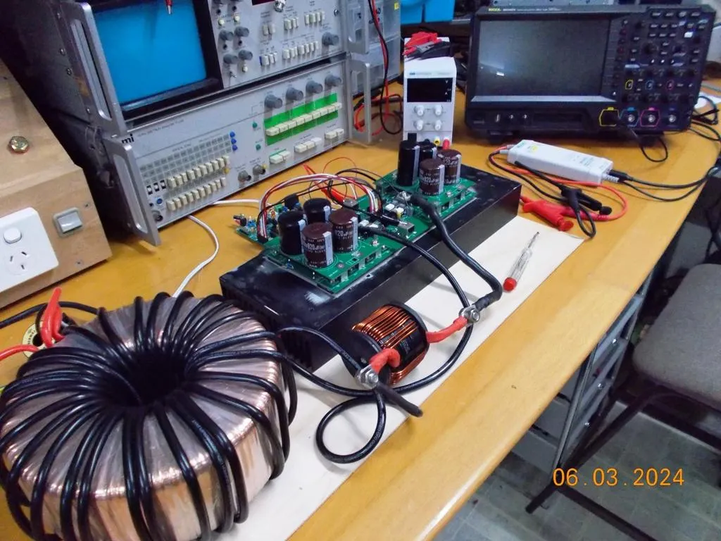
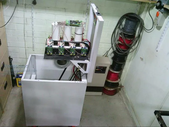
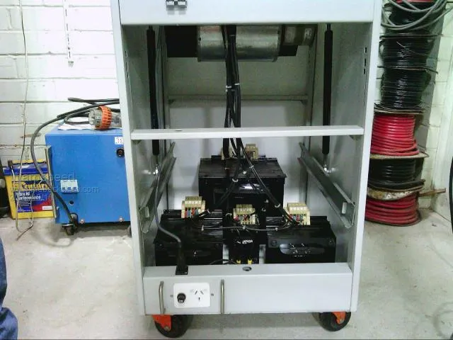
Here's one of his prototypes
Poida has also been on the Back Shed for many years and has been instrumental in adding microprocessor control for inverters and solar charge controllers being designed in the group.
His Arduino Nano programs have been used on many of the inverters built … and now also the WG Inverter.
His 150V 45A MPPT has many, many examples built all around the world.
I have four of them and have clocked a combined 20MWh of power production through them in the last 20 months.
Poida: 02/06/24
“It's one thing to see amateur people do a few things (think: me) and deliver a result that sort of works, if you hold your tongue right and have a coupl'a beers and accept fireworks and stuff.
It's an entirely other thing to have an E.E. of many decades offering a solution. This is Wiseguy. His inverter design is going to kick ass and it will not blow up.
It has most excellent FET Gate drive and there is NO shoot through at all. Not even a tiny bit. This is the best I have ever seen. I am lucky to be involved in a professional project.
If you want a good inverter, I would go for this project. It's just going to run and run and ran for years.”
Like to Build Your Own WG Inverter ??
Wiseguy is currently in the process of making available all the gerber files for his boards, from one or two locations.
Then anyone can order whatever they want individually … or organise a group buy to get the price way down.
Wiseguy 02/12/25:
FYI I got quotes for 5, 10, 15 & 20 of the Power PCBs including shipping the results are below
WG30R2 PCB (Main Power board)
5 = $100 total (inc ship $48) per ea $20.00 w/o shipping $10ea
10 = $121 total (inc ship $60) per ea $12.00 w/o shipping $6ea
15 = $132 total (inc ship $71) per ea $ 8.80 w/o shipping $4ea
20 = $198 total (inc ship $83) per ea $ 9.90 w/o shipping $5.75ea !!
If the other various PCBs are purchased in prototype quantities (5) each type is under $7 (manufactured and delivered worldwide I believe), but if you were to add them to the Power PCBs order, freight can increase the overall freight cost rapidly.
My advice, a few Aussies? get together and order the power PCBs to share the more expensive 2oz PCBs and the cost.
Else if someone lives overseas just buy min. quantity of 5 & get over it, they now have 5 power PCBs for ~ $100!
All the rest are best ordered by each person separately local or overseas, the cost of the remaining boards is then ~$35 total for the 5 types & 5 of each (a few spares).
For anyone wondering what the 2oz refers to ... it is simply the thickness/weight of the copper cladding on the pcb.
PCBs are normally 1oz ... but because of the massive currents involved in an inverter like this ... it is helpful to have thicker copper to help reduce voltage drop and heating effects.
It also saves having to run extra wires or copper bars across the surface to reduce resistance.
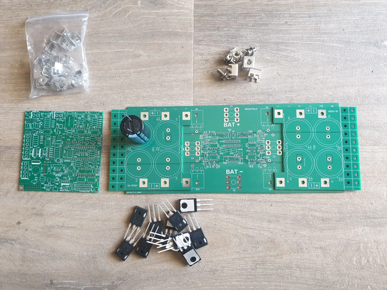
Soooo ... to join the homemade-inverter-builder’s-club, this is what you’ll need.
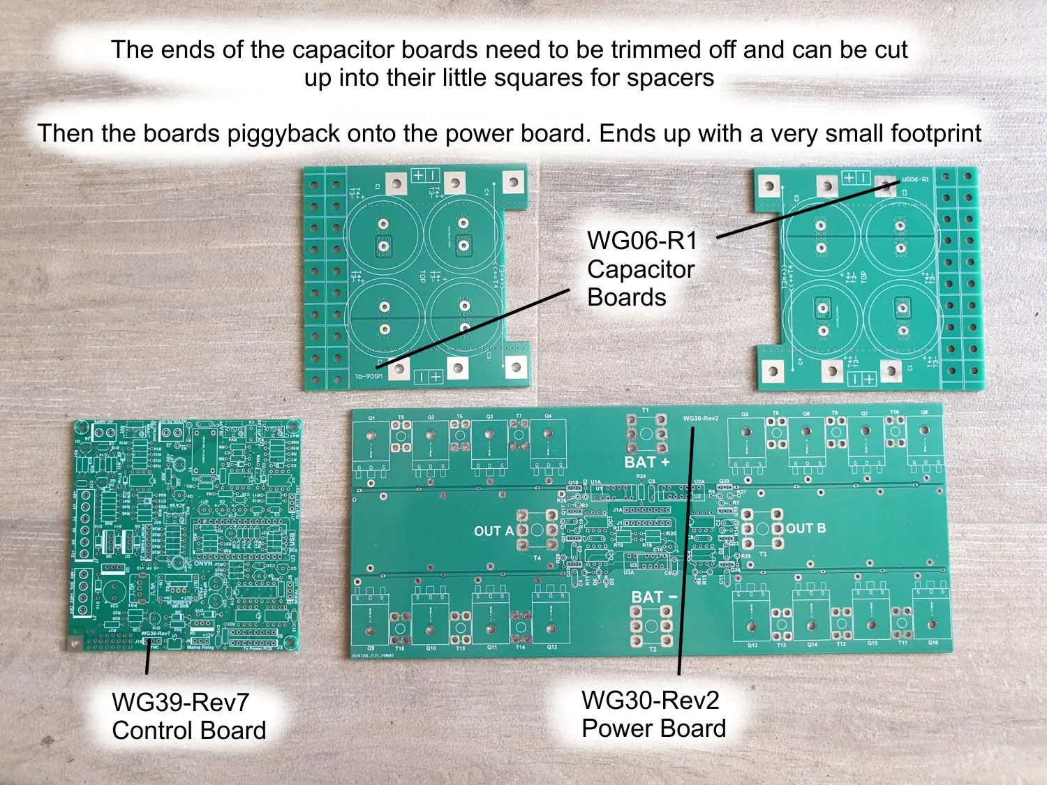
Power pcb (WG30-Rev2) 260mm x 108mm (2oz Copper)
Controller pcb (WG39-Rev7) 100mm square
Bulk Capacitor pcb x 2 (WG06-R1) 100 x 100mm (2oz Copper)
Toroid
Choke x 2
Display 20 character x 4 line
Arduino Nano x2 Microcontroller
Fan/s For Toroid and Heatsink
FETS HY5608 Mosfets
Capacitors 4,700uF or 10,000uF x 63V
It is recommended to buy a spare pair of Bulk Capacitor boards (WG06-R1) and fit some low value caps to use while setting up or during any fault finding. A lot more forgiving if there are any faults.
The Controller board houses the Arduino Nano Microcontroller that takes care of the control and monitoring of the inverter.
... and the controller connects via 3 wires to the 20 character x 4 line Display ... driven by a second Arduino Nano.
While HY4008 Mosfets were used for many OzInverters, HY5608 Mosfets are recommended for the power board.
Wiseguy
“I do advocate the use of HY5608s for the Power PCB’s, they have proven to be extremely robust, each FET is roughly equivalent to two HY4008’s in parallel.”
Just a Word of Caution:
Counterfeiting of electronic components is a real thing and can cause a lot of heartache if you happen to fall foul of it.
There appears to be a general consensus that LCSC Electronics are a reliable supplier, particularly of HY4008 and HY5608W mosfets ... so if you want confidence that you are receiving genuine parts, give them a try.
Toroids:
We have the same requirements for a toroid with a Wiseguy inverter as for an OzInverter.
So anyone who can find an old 3kW Aerosharp or two will be set … or maybe three 2kW Aerosharps.
KeepIS has built a couple of inverters using three 2kW Aerosharp toroids stacked together. In his case, he removed the outer winding on each toroid … and then hooked the remaining windings in series. Followed by winding the heavy primary winding around them all.
If you want to spring for new, AEM Cores in Adelaide can provide what ever size toroid core you might desire depending on your required output … though costs will be substantial.
Chokes:
Two chokes are required … one on each end of the primary winding.
Six toroidal ceramic cores are stacked together and have four or five turns wound through them.
KeepIS favours using a slightly lighter gauge wire for the chokes than the primary winding … to add some resistance … which helps reduces the load/shock on the mosfets.
WG Inverter Bare Boards
WG Inverter Capacitor Boards in Place
Power Board 260 x 108mm and Control Board 100 x 100mm
Wanna run 24V or 36V instead of 48V …
As mentioned above ... with this controller you can run a 24V or 36V or 48V inverter with essentially no changes to the electronics.
Only the Toroid and the choke need to be changed to suit the DC input voltage and power output requirement.
And for something really wild …
With the right toroid and chokes, a WG Inverter should happily run up to 6kW loads … BUT ... add a second power board, toroid and chokes … you can turn it into a 12kW inverter … all running off the one controller.
Trendsetter that he is ... KeepIS has built one of these as well ... using a total of six 2kW Aerosharp toroids ... three on each side.
Read all about it in the latter part of this thread over on the back shed.
Download these pdf's to see the parts needed to build the boards for a basic 6kW WG Inverter
Parts List ... BOM - WG39R7B - WG44R2 - WG48R1 pdf
Parts List ... BOM - WG30R3 - WG06R pdf
Click Circuits to Open High Resolution Versions
WG Inverter Overview
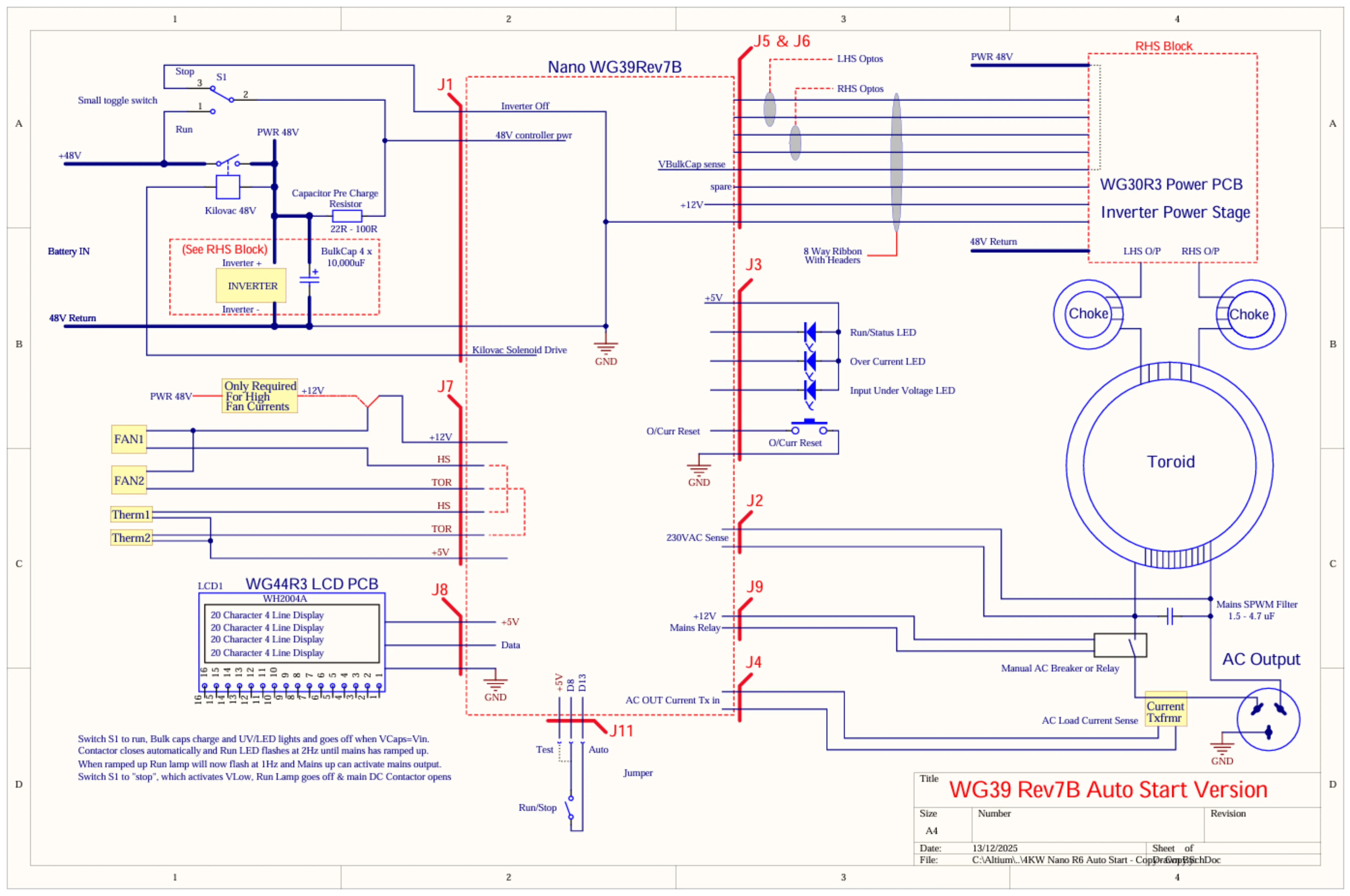
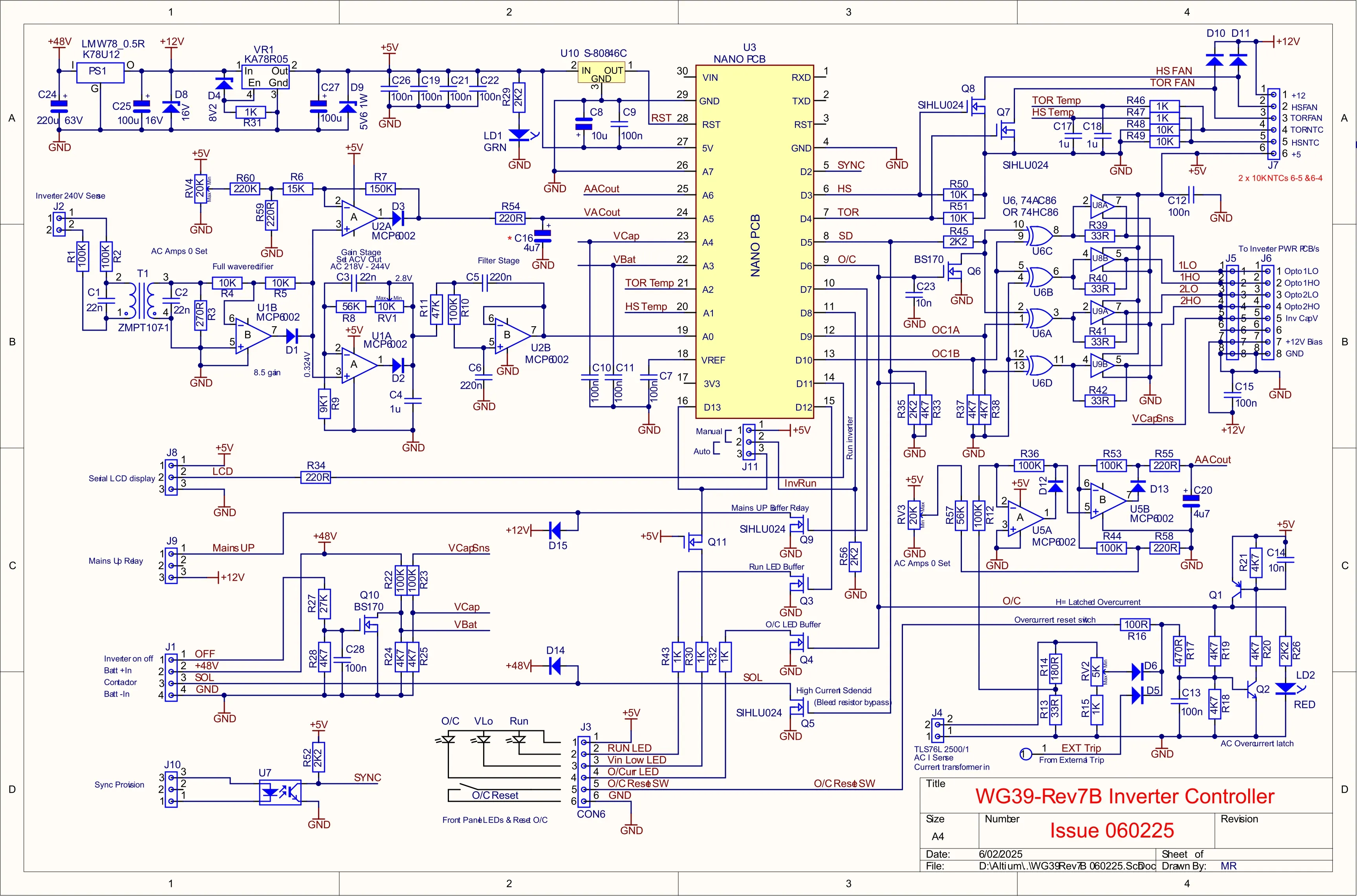
Controller Circuit ... WG39-Rev7B
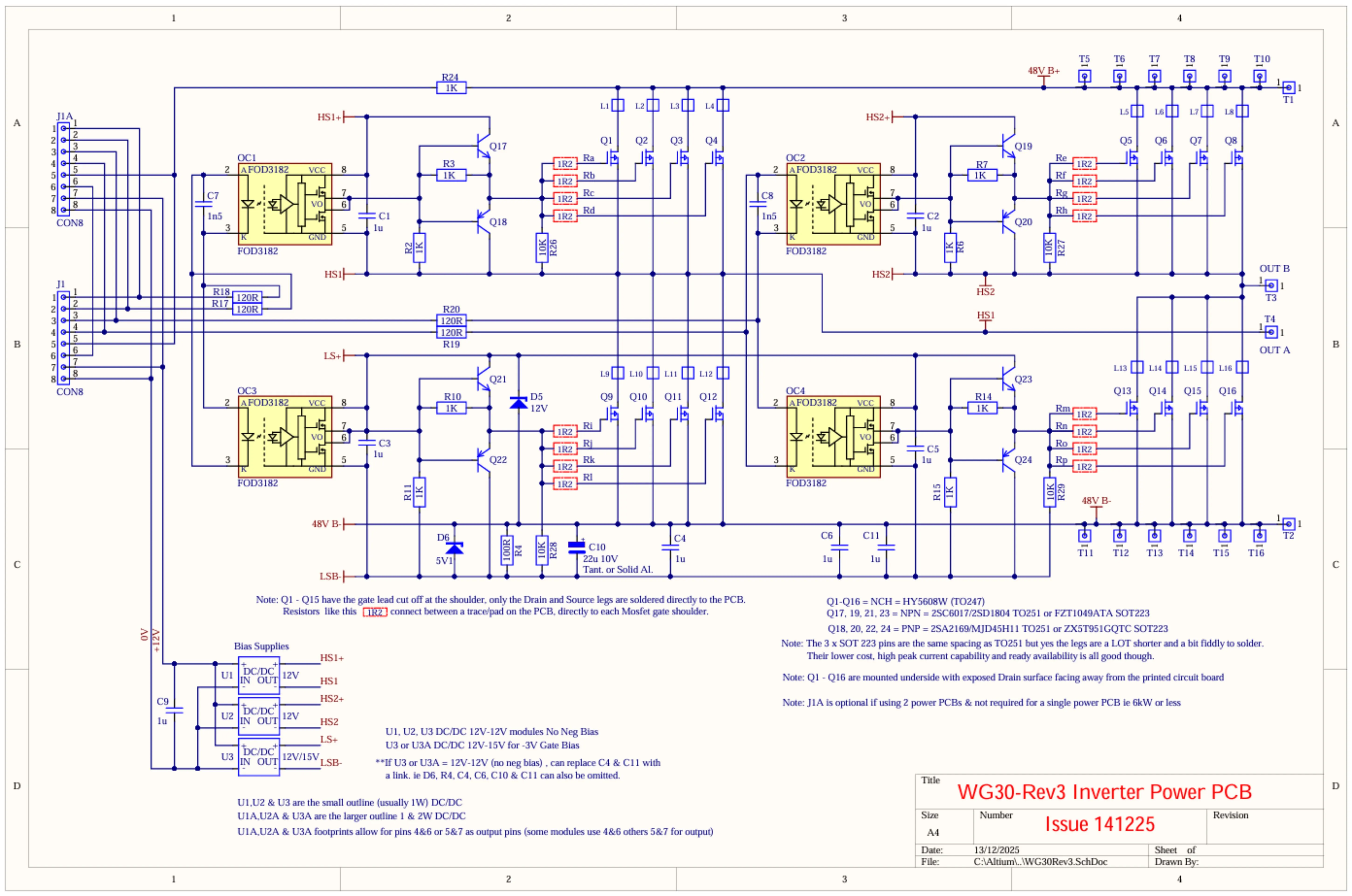
Power Board Circuit ... WG30-Rev3
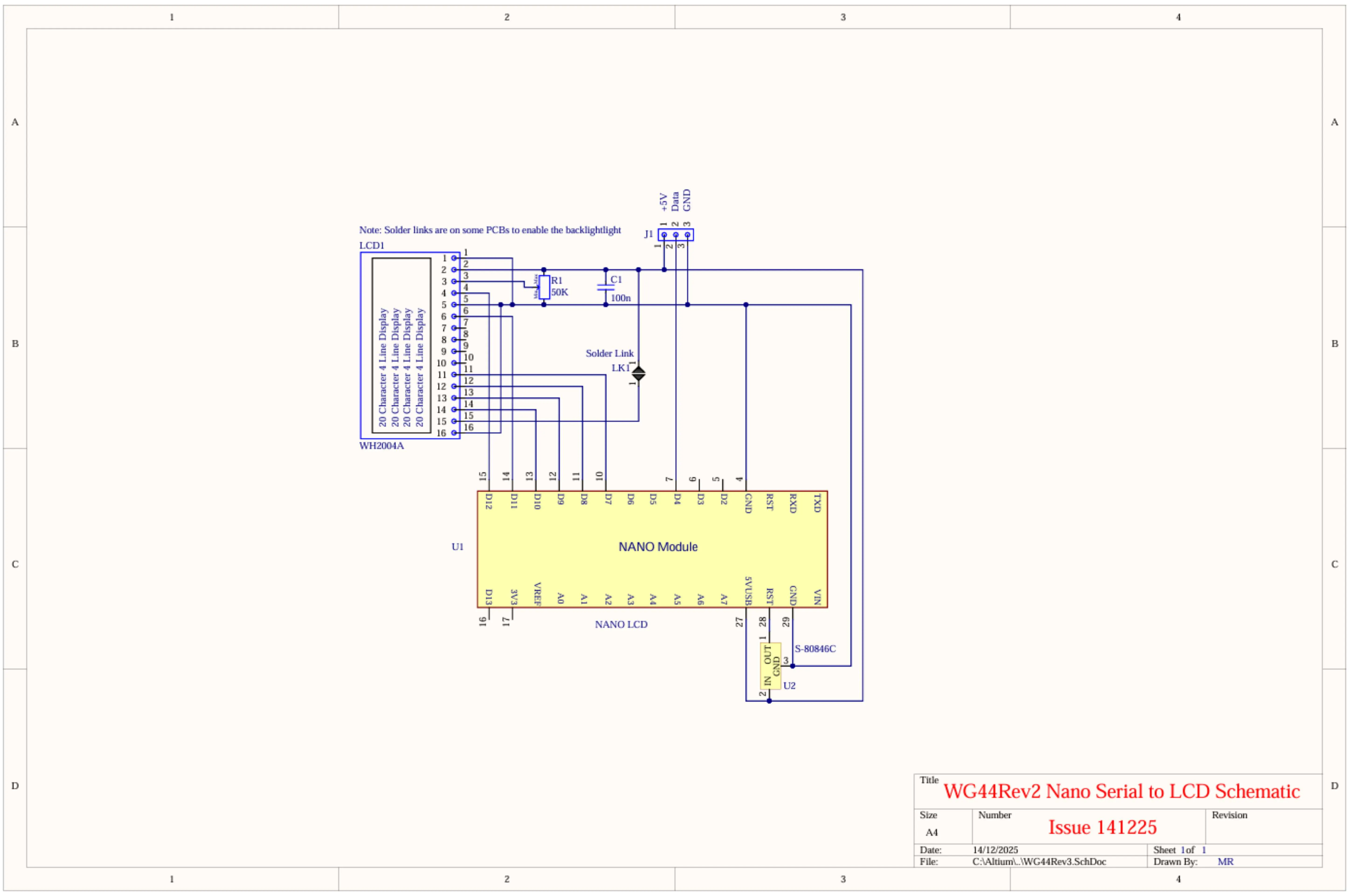
Nano Serial to LCD Circuit ... WG44Rev2
I'm waiting on some photos from KeepIS to replace those below
Some Random Photos
To see more detail right click and "Open image in new tab"
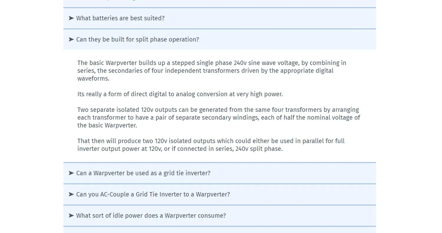
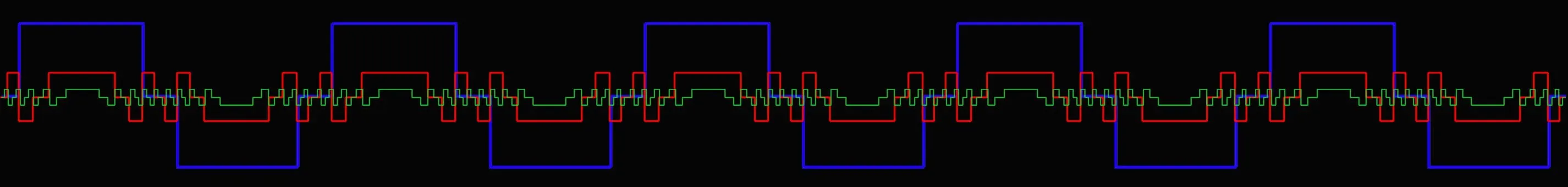
How Split Phase works on a Warpverter
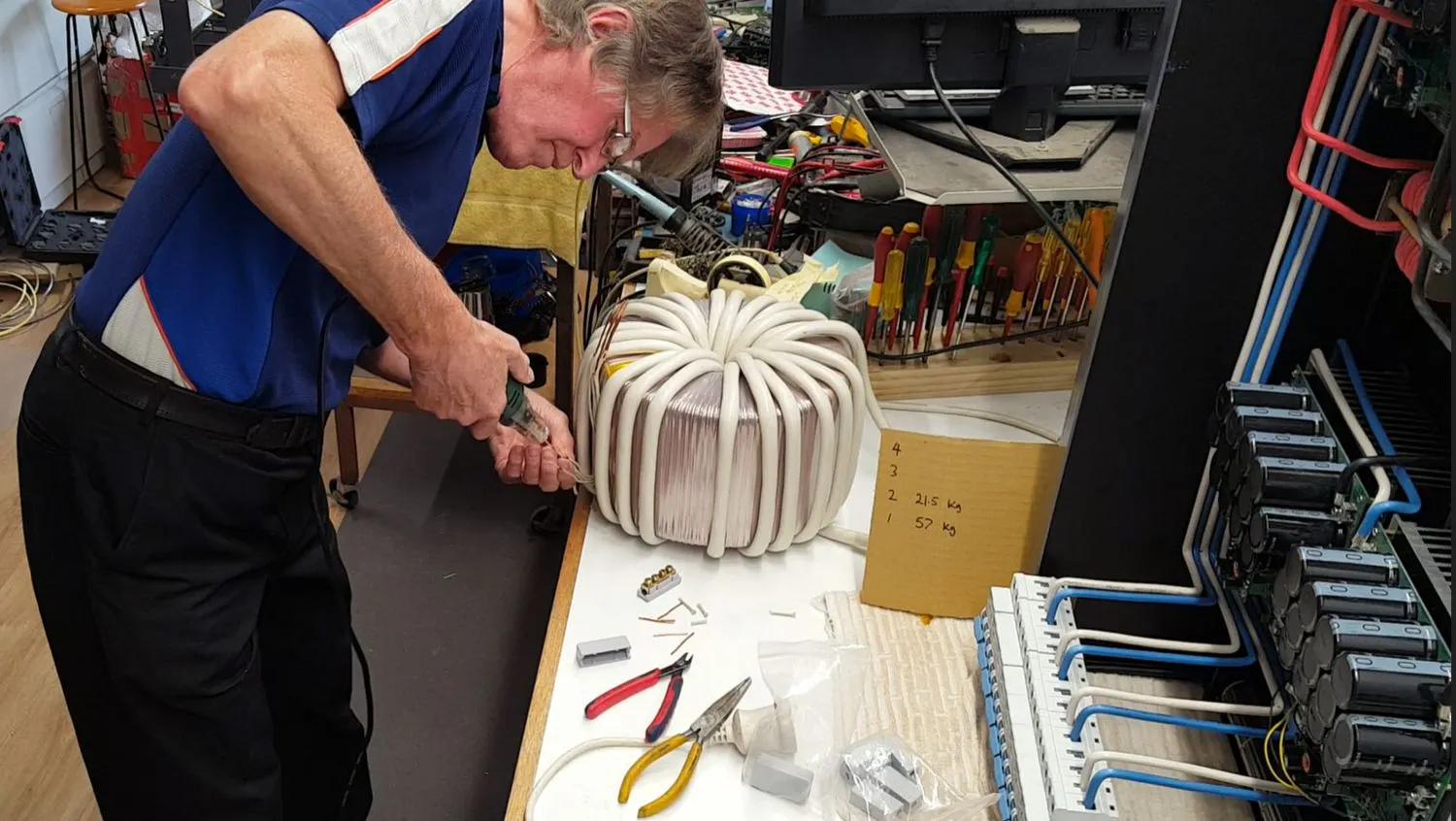
Stripping the enamel off the ends of the individual copper wires using a DF-8 electric wire stripper ... available from Amazon or aliexpress
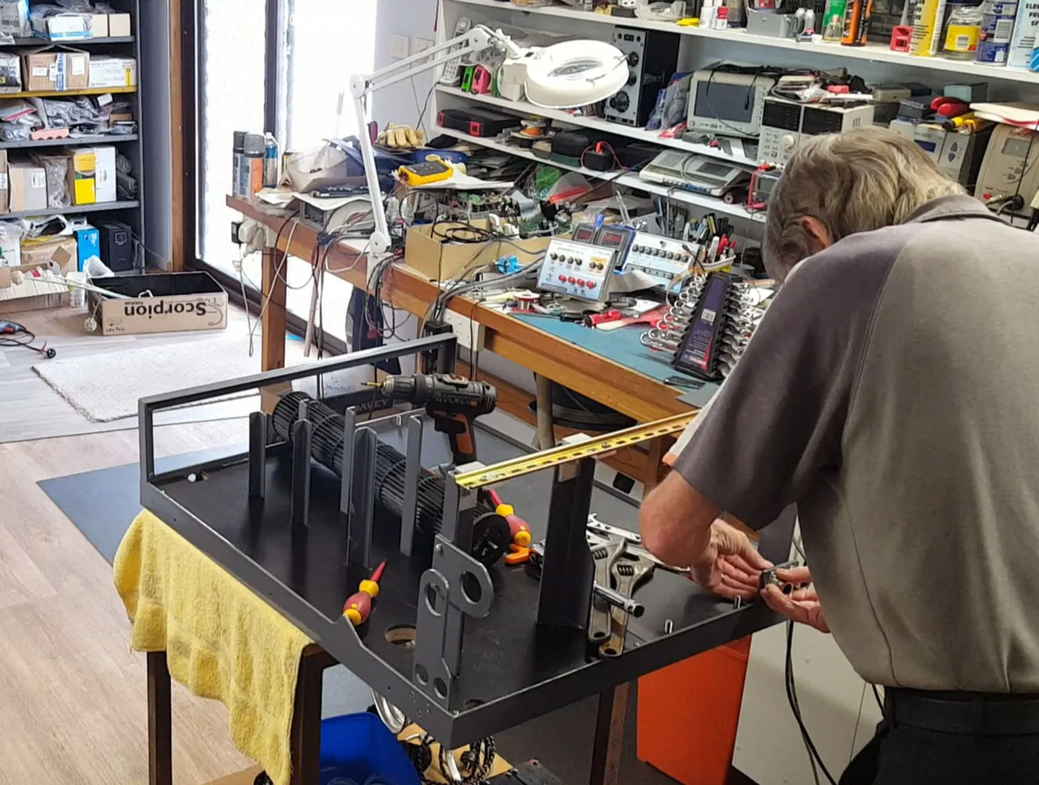
Starting the final assembly
Bit heavy to lift at 57kg, so just rolled into place
Lor
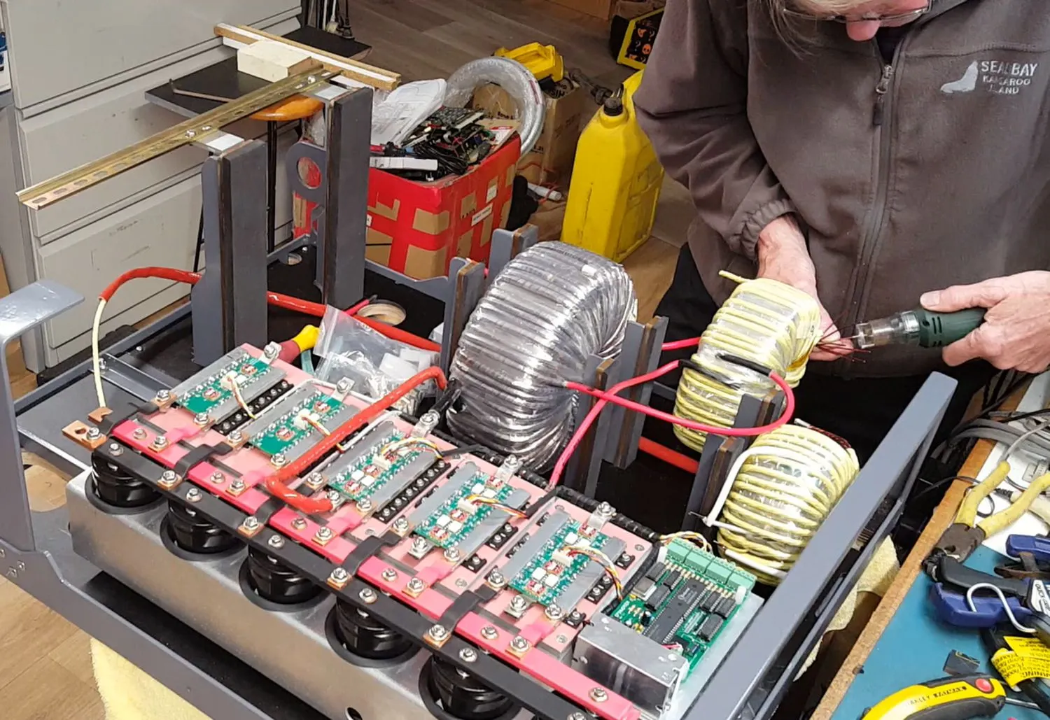
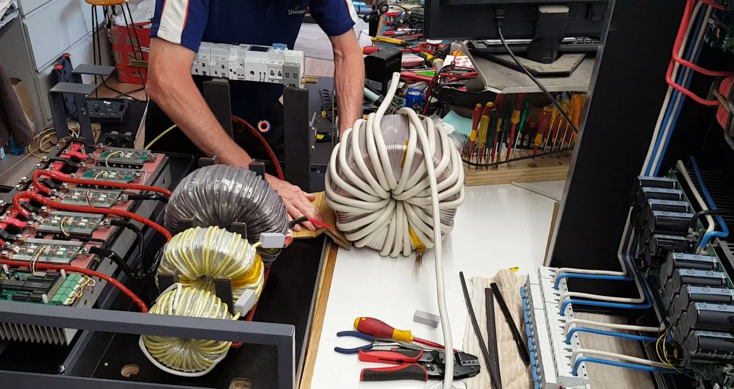
Stripping the wire enamel off the "Small" toroid winding ends
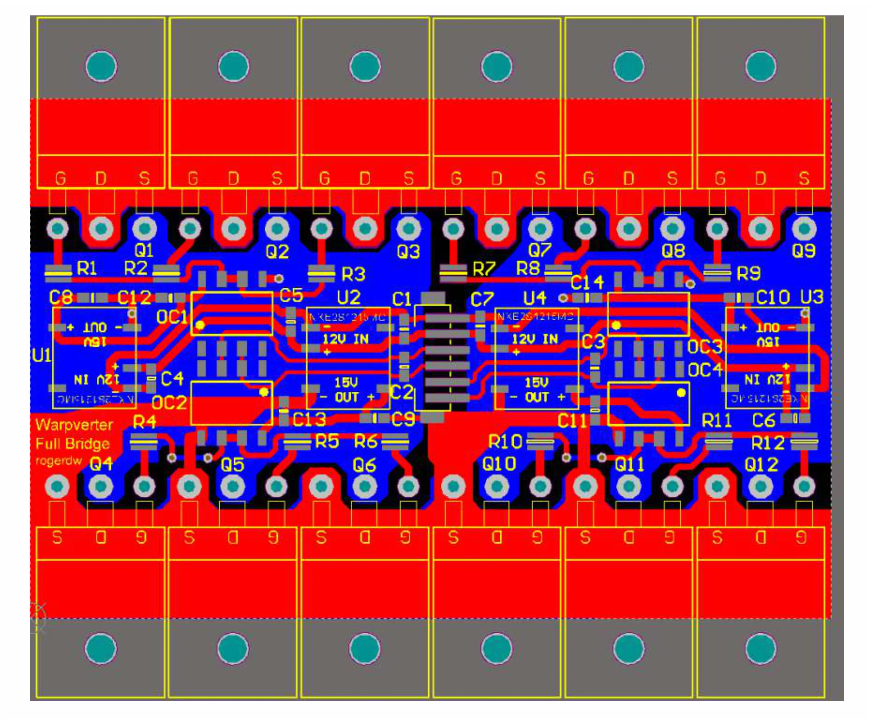
Warpverter Full Bridge board layout
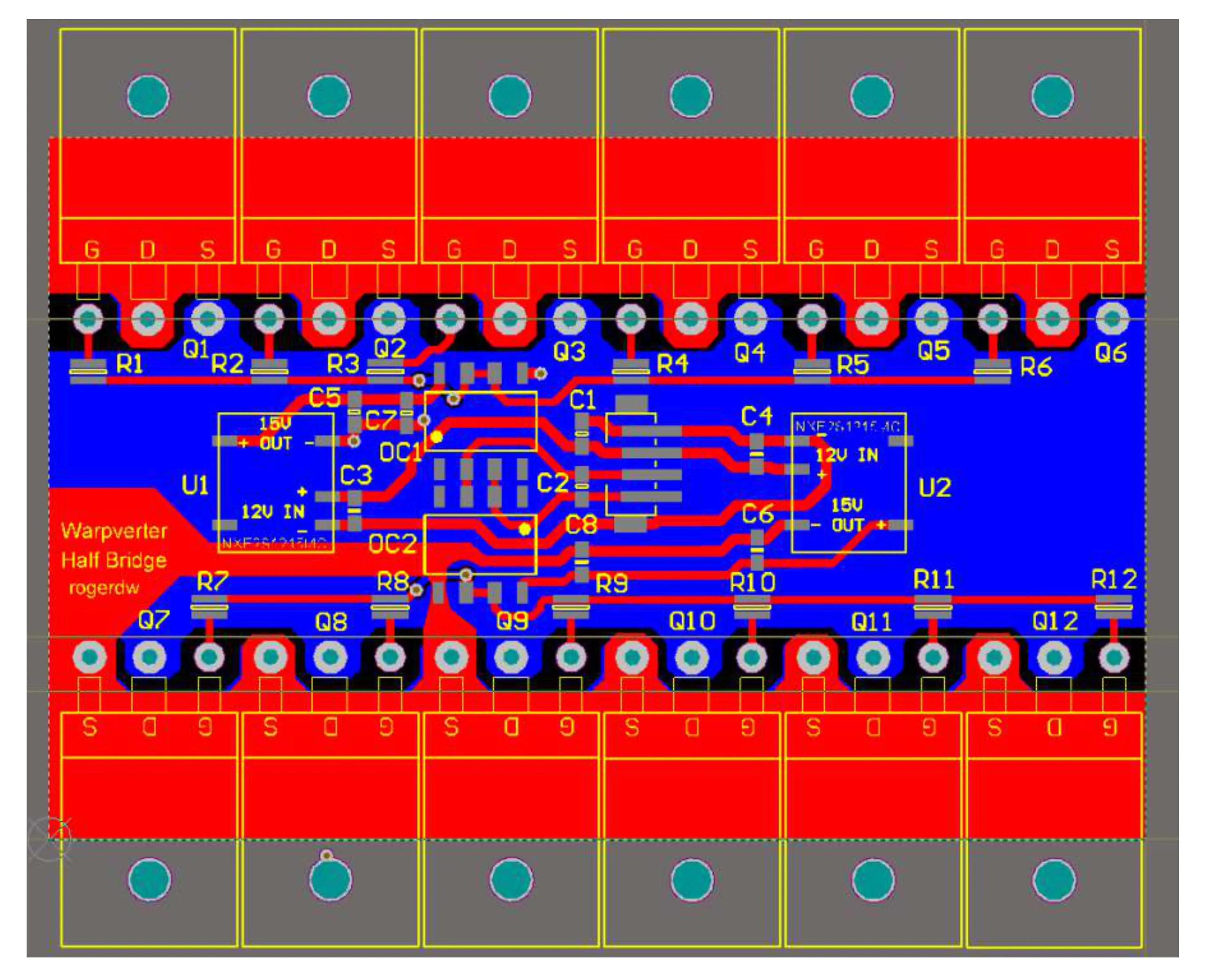
Warpverter Half Bridge board layout

Lorem ipsum dolor sit amet, consectetur adipiscing elit. Quorum altera prosunt, nocent altera.
Contact: Visit this thread on diysolarforum and message Warpspeed or rogerdw
© 2024 Warpverter.com - All Rights Reserved. Terms of Service: Privacy Policy: