Warpverter
A Serious Electronic Project For The Expert DIYer
Transformer Design
Nailing down some requirements.
The starting point is first to determine the minimum dc input voltage the inverter will ever see.
That will be influenced by the number of battery cells and battery chemistry.
We have a very wide 2:1 input voltage range available, so its recommended that the minimum design input voltage be set quite low so that the Warpverter can work through sudden short term load surges when the battery voltage is getting down near full discharge.
Next step is to decide on a maximum output power goal, and convert that into required inverter output current.
The transformer design secondary voltages we can assume will be 225v, 75v, 25v, and 8.33v.
These voltages must all decrease in precise steps of 3:1 so that when these voltages are finally combined in series, the voltage steps will all be as even as we can make them.
These target voltages were chosen to give nice round numbers which keeps the math neater.
If all four inverters switch on together in the same direction, these voltages add directly to create a theoretical 333.33v peak output voltage across all the secondaries. And the rms value of the resulting sine wave will be 235.7v
It will be appreciated that a final working Warpverter has an output voltage adjustment potentiometer and the actual real working output voltage can be adjusted above or below the theoretical 235.7v as required. But we need some initial design target voltages to calculate the exact transformer turns ratios required to create the precise 3:1 voltage differences in each of our four transformers.
So at this stage we might have come up with a hypothetical design requirement that the largest transformer will have a 40 volt primary, and a 225v secondary that needs to carry 30 amps at full rated power.
These will be rectangular waves of various continually changing frequency and duty cycle in the smaller transformers, and all the on-line transformer calculators use 50/60Hz sine waves to calculate flux density. We can just assume the transformer voltages are all 50/60Hz sine waves to greatly simplify things. All the assumptions will be on the safe side, and this short cut definitely does work !
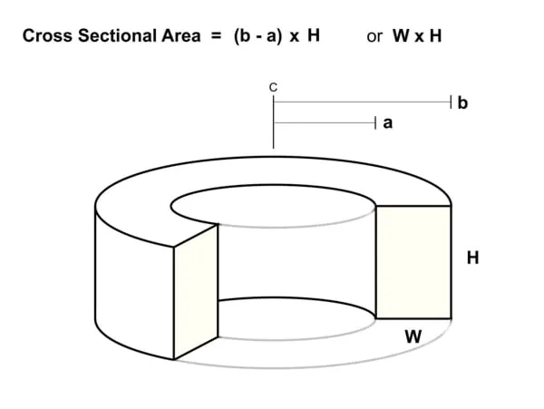
Next step is to measure up our toroidal core (or cores if you plan to stack two or three).
Its the total magnetic cross section around the toroid we are interested in, in square cm (height x width).
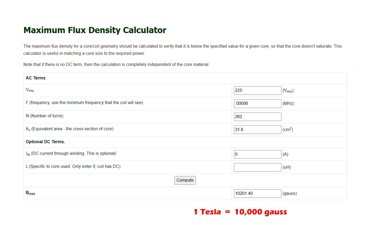
We can then use one of the many on line transformer flux calculators to calculate the flux in the core.
Enter the volts rms (225)
Enter the frequency (.00006 Mhz) for 60 Hz, note there are four zeroes.
Enter the number of turns (first wild guess maybe 250 turns ?)
Enter the magnetic cross sectional area in square centimeters.
Click “compute”
It will come up with a figure for flux density in the core.
By trial and error, adjust the turns count to get reasonably close to one Tesla flux density. It does not need to be super exact.
In our hypothetical example here, let’s assume it comes up with 262 turns = 1.02 Teslas.


Now we need to end up with a pretty exact voltage ratio of 40v primary to 225v secondary as established earlier.
If we have a 262 turn secondary, the primary turns required would be 262 x 40/225 = 46.577 turns.
So let’s try it first with 47 turns on the primary.
Required secondary 47 x 225/40 = 264.375 turns.
Then with 46 turns on the primary.
Required secondary 46 x 225/40 = 258.75turns.
Either will work.
If building for split phase an even number of secondary turns will be necessary because we need to split the total secondary count into two seperate windings.
If its for single phase, either 258 or 259 would work.
Lets’s go for 258 secondary turns in this example.
That will get us a secondary voltage of 40/46 x 258 = 225.2v which is extremely close to the ideal 225v.
As our steps are each 8.33v anyway, a 0.2v error is negligible.
Now the next question is, can we actually fit 258 turns onto our toroid of wire thick enough for our desired power goal, so it only uses up half (or less) of the available area through our hole ?
This is where the size of the toroid becomes important.
If it won’t fit, we either need to get a larger toroid, or stack cores.
Stacking two cores requires only half the turns so we can then fit thicker wire and get a higher power rating with multiple cores.
Recommended current density in the wire for both primary and secondary will be 4 amps per mm square. That will run quite hot at sustained high power, but not dangerously hot, and it will do it with just convective free air cooling.
Domestic inverters generally run at pretty low average power, with short bursts at full power.
Massive surge loads of multiples of rated power are possible, because the large mass of copper and steel takes a relatively long time to heat up
Its ultimately the maximum safe temperature rise that sets the power rating of a transformer, and that is a bit of a judgement call. But 4 amps per mm squared works fine for continuous full rated power for endless hours.
Selecting the wire size.
Our hypothetical transformer will have a 30 amp secondary, and we are aiming for a current density of 4 amps per mm square. So we need about 7.5mm square copper in the secondary.
There is a fairly narrow window of wire sizes that are practical for toroid winding.
Wire stiffness increases to the fourth power of wire diameter believe it or not! Wire of twice the diameter is 2x2x2x2 or sixteen times as stiff.
Experience of both myself and others suggests that 1.8mm diameter wire is about the optimum choice, and moving up or down in wire size very far tends to make the whole task more difficult.
Any thinner and the current rating decreases. Much thicker and it rapidly becomes extremely user unfriendly. 1.8mm wire works out to ten amps per strand, so three seperate secondary windings 258 turns, connected in parallel would be about right for our hypothetical 225v 30 amp secondary.
For split phase operation we will need to have two seperate 112.5v secondaries instead of a single 225v secondary.
For that, 129 turns per half secondary, each consisting of three strands of 1.8mm diameter wire.
Planning the windings.
We need to divide the hole in our toroid into roughly two equal areas. When the secondary of the largest transformer has been placed on the toroid, the diameter of the remaining hole should then be 0.7071 times the original hole diameter, or reasonably close.
From that, we can see that the very last layer to go onto the secondary winding is going to have the smallest circumference.
If for example the original toroid hole was 120mm diameter, the last final layer of the secondary will have a theoretical diameter of 120mm x 0.7071 = 84.85mm.
The circumference of that final layer will be 84.85mm x 3.142 = 266.6mm.
If luck is with us, we should in theory be able to fit 266/1.8 = 148 turns on that last layer.
We need to fit on 258 turns per winding, so its going to fit comfortably into two layers for the tightest last winding.
The very first winding to go on will have the full 120mm hole diameter available to work with, or a circumference of 377mm.
In theory that could take 209 turns of 1.8mm wire in one layer, so we still need two layers per winding.
So for our hypothetical transformer design, the secondary will require six layers of wire, with 129 turns evenly spaced right around the core. A single phase transformer three 258 turn windings each of two layers.
A split phase transformer, six windings each of 129 turns in six layers.
Now our hole starting diameter was 120mm in this example. And our finished hole size with the secondary windings complete should end up leaving about an 85mm remaining hole for the primary. The build up of six layers of wire plus insulated layers will be 17.5mm maximum.
That allows 2.9 mm per layer. As we are only using 1.8mm wire, there is plenty of room for insulation and slightly bulging layers of wire. So it should all fit onto the core.
Your numbers will vary hugely from the above example, but if you follow the same method, it will give you some kind of a plan to work towards knowing there will be sufficient space on the core to fit enough turns with thick enough wire to do the intended job.
Planning the primary.
In this example we ended up with an 85mm hole, and we need to fit on 46 turns.
Primary amps will be secondary amps x turns ratio. 30A x 258/46 = 168 amps
Current density four amps per mm squared, so 168/4 = 42mm square wire for the primary, or nearest suitable size.
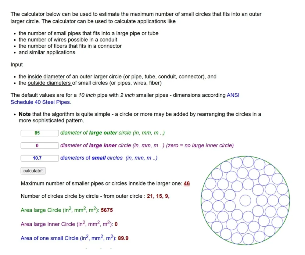
There is a circles within circles on line calculator that will tell you the largest diameter wire that will fit 46 turns through an 85mm hole. The oracle says 46 turns of 10.7mm diameter wire will fit.
What I suggest you do is get some 10mm diameter rope and wind on 46 turns of that to get the length. The wire is horrendously expensive, so its worth buying just enough.
In this example it needs to be about 42mm sq, and no larger than 10.7mm outside diameter.
Fine multistranded auto or marine battery cable, or welding cable is ideal. The welding cable is usually double insulated and may need the outer layer stripped off, but the advantage is its sold by the metre, and the insulation is rated for high temperatures.
Looking at some wire tables, American 0 or 1 gauge cable looks about right for this example. In Australia Tycab make 39.55mm sq cable with an outside diameter of 12.1mm unfortunately.
That might work if the final hole ends up being larger than 85mm, which is highly likely in this example, because the secondary uses up somewhat less than half the hole area.
Also, this very fine flexible multistranded wire squashes down very easily at the points of contact. The circles within circles calculator assumes hard unyeilding rigid circles. So the thicker wire may fit in this example with a bit of determined effort.
This design example has ended up being a pretty tight fit on the core.
Its a questionable result.
It might be advisable to start from scratch and go through the whole pencil and paper exercise again with a slightly larget toroid which will reduce the number of turns required, and that will make a very large difference to how the numbers turn out, and how easily everything fits.
There is no other way to design transfomers, its always a trial and error process juggling numbers around until something practical that can actually be built results.
The second transformer design would go through the exact same process.
40v primary in this example, 75v secondary, at 30 amps.
The second transformer may be a voltage step up or a voltage step down transformer, depending on battery voltage.
Its always the higher voltage winding that goes onto the core first.
That produces the flattest winding, over which the more lumpy lower voltage winding can be wound.
The two smaller transformers will always both be step down, so the primaries go on first.
Otherwise the design process is pretty much the same.
The individual voltage steps will be 8.33v, so try to keep all the seconday voltages as close as you can, preferably within one volt, and that should not be too difficult.
Try out the circles within circles calculator

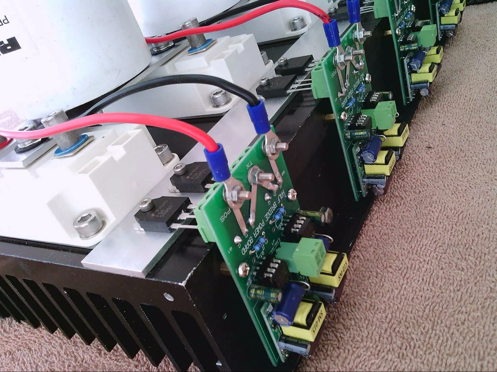
Tony's 5kW Warpverter Output and Heatsink

Contact: Visit this thread on diysolarforum and message Warpspeed or rogerdw

© 2024 Warpverter.com - All Rights Reserved. Terms of Service: Privacy Policy: