Warpverter
A Serious Electronic Project For The Expert DIYer
Half Bridge boards, bill of materials
Gerbers for ordering Half Bridge boards are available from the downloads page. Eight boards will be required.
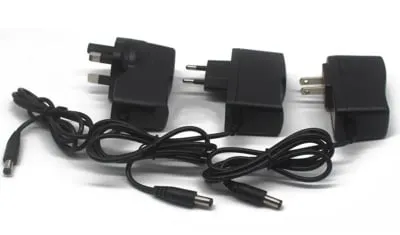
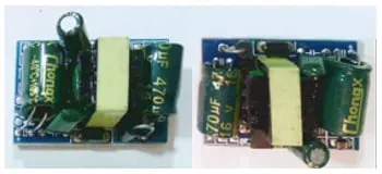
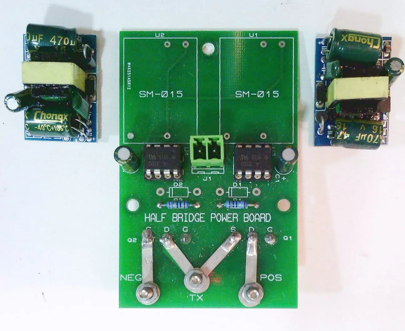
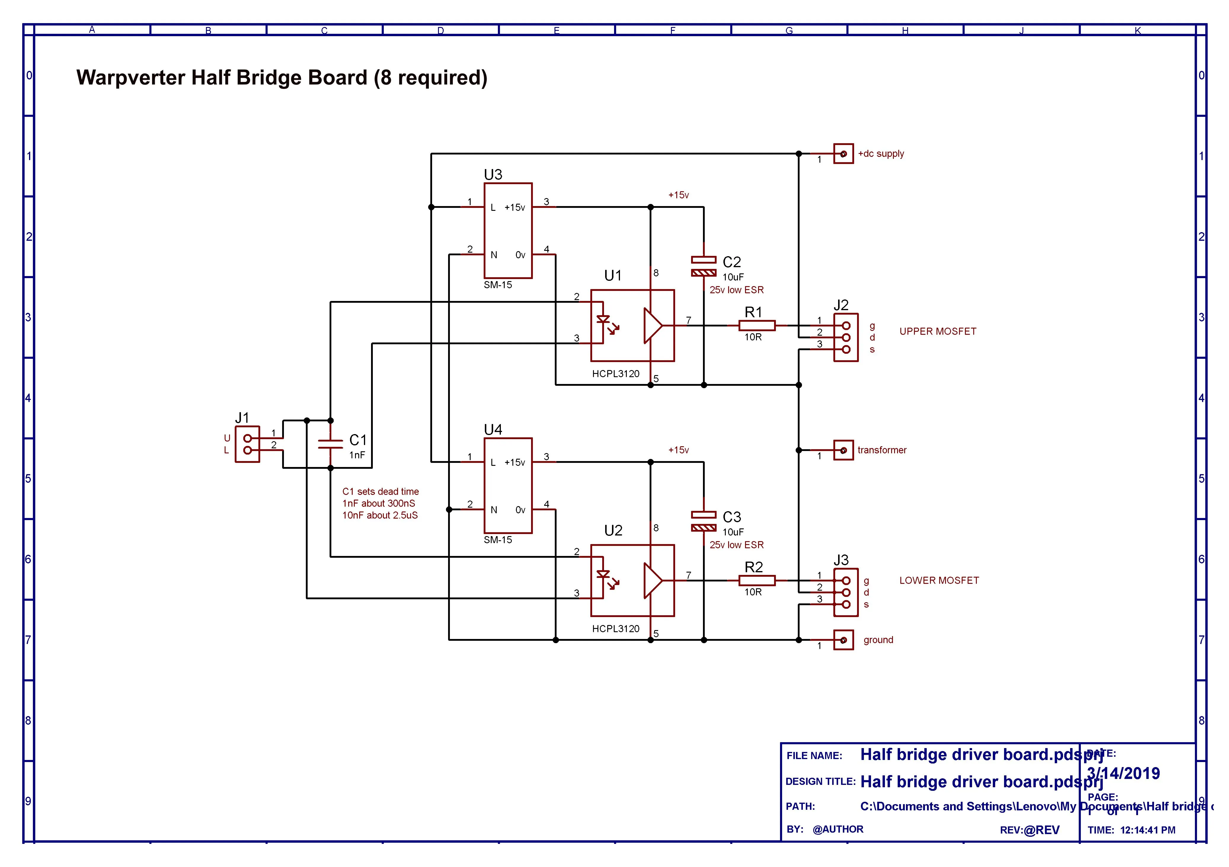
U1 and U2 are those small Chinese two dollar circuit boards used in 12v dc wall packs, and are readily available from e-bay and Ali. There are two per board, eight boards, sixteen required total


U3 and U4, HCPL3120 two amp opto isolated gate driver chips, two per board, sixteen total.
Two 8 pin machined contact IC sockets 0.3” wide, eight boards, sixteen required total.
C1 and C2, 10uF 16v low ESR electrolytics, two per board, sixteen total.
C3 dead time capacitor, these will need to be selected to suit the switching devices used. See Builders notes about dead time.
R1 and R2, 6R8 metal film resistors 1%, two per board, sixteen total.
These limit max gate drive current to two amps peak for driving individual mosfet or a large IGBT.
If running multiple parallel devices you will need one resistor per gate.
For instance, driving four large parallel mosfets requires four 27 ohm gate resistors to limit total peak current to two amps when driven from 12v.
J1 Two pin straight socket for screw terminal block. Pin spacing 0.15” or 3.81mm.
Two pin straight screw terminal plug to suit.
There are straight and right angle plugs, and straight and right angle sockets. We require straight plugs and straight socket, two per board, sixteen total.
Q1 and Q2 could just be a mosfet or IGBT soldered direct to the board.
A much better way would be 0.2” or 5.08mm three way screw terminal blocks, straight or right angle (depending on heat sink configuration) soldered onto the board.
For monster IGBT half bridge power blocks, a three pin plug in screw terminal block works out pretty well.
It is recommended that the source and drain tracks of Q1 and Q2 be beefed up to carry high current by soldering copper lugs on both sides of the board over the tracks, to the 4mm power and transformer terminals, POS, NEG, and TX.
That will make the board virtually indestructable, even if its just a one ounce board.
The lugs to use are tinned plated copper (15mm between hole centres) available from X-on electronics, part number 60-2814-51/0030 available in multiples of ten.
You will need four for each side of the board, and for eight boards, 64 lugs total.
This is a far more robust and lower cost solution than just specifying much thicker board tracks, which would probably still burn up anyway.
Click Circuits to Open High Resolution Versions
Contact: Visit this thread on diysolarforum and message Warpspeed or rogerdw

© 2024 Warpverter.com - All Rights Reserved. Terms of Service : Privacy Policy :

