Oops! Sorry!!


This site doesn't support Internet Explorer. Please use a modern browser like Chrome, Firefox or Edge.

Warpverter

A Serious Electronic Project For The Expert DIYer

Transformer Winding

If you’ve ever wanted to know how you could wind a toroidal transformer at home and without a fancy winder … there are a few options.

Some people use an empty solder reel or something similar to fill up with copper wire … though they don't generally hold much and can require refilling ...  and then joins will be needed before the winding is finished. As the hole gets smaller it can become too small to fit the reel through.

Others use a “shuttle” … a length of wood with a V in each end, with the copper wire wound on it to feed through the hole. As the hole fills up, that also gets harder to fit through and you may end up having to join on extra wire to make the distance … though extra long shuttles can fit a lot of wire.

I prefer a third method … using a hoop. A kids hula hoop to be exact.

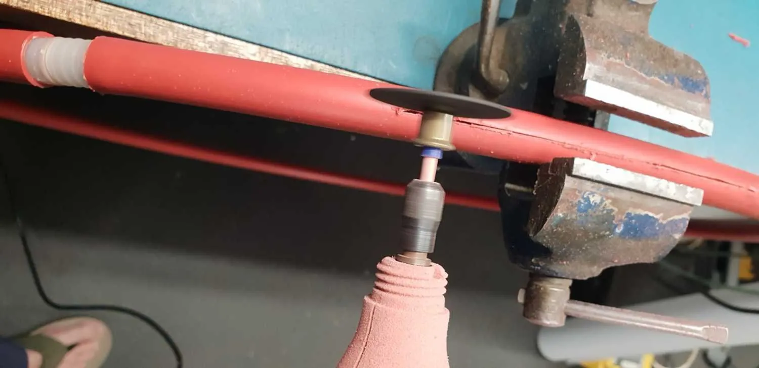
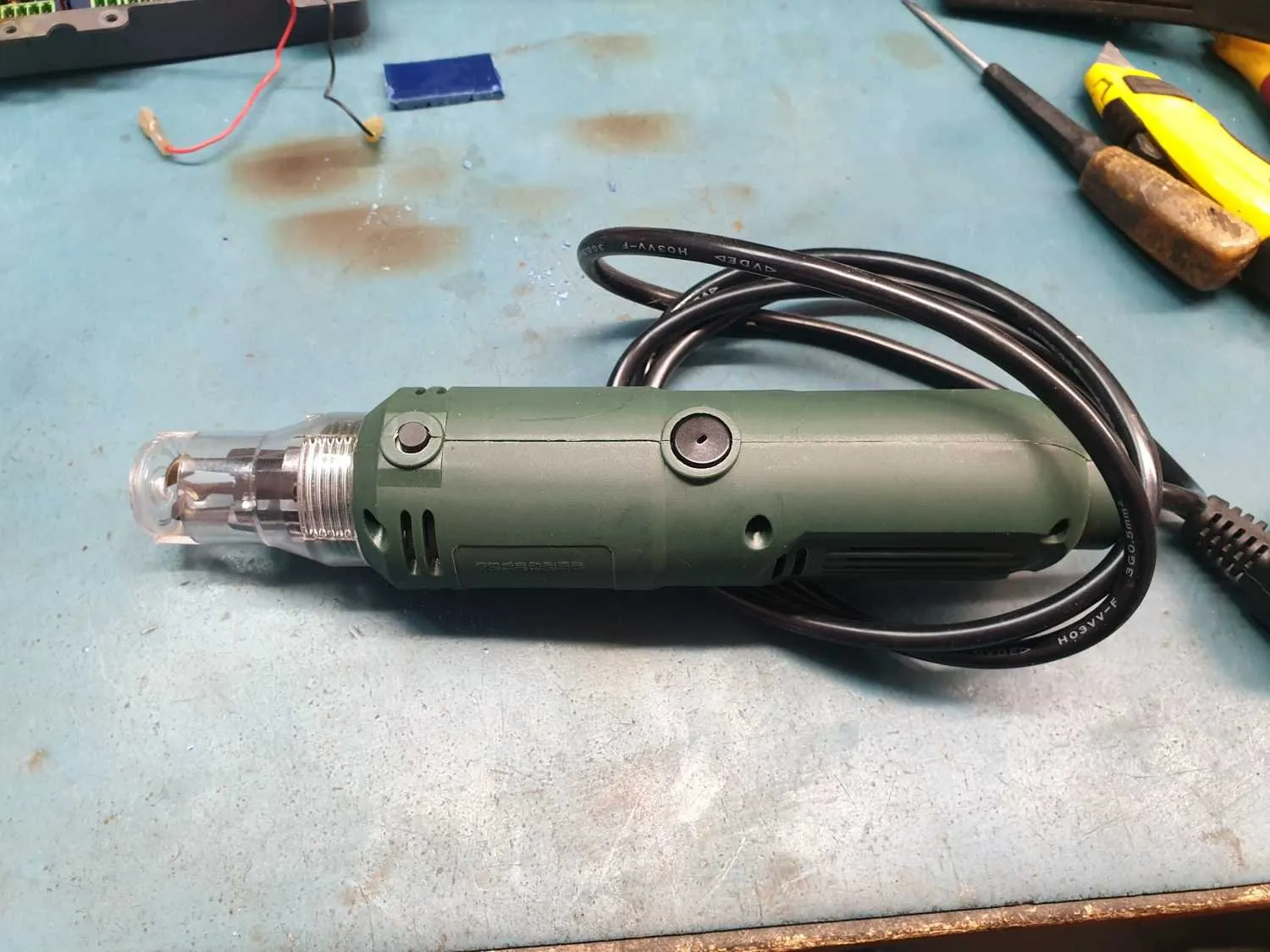
I used a Dremel to cut a slot all the way around the outer circumference ... though a hacksaw or fine bladed hand saw would work just as well.

 The next step was to cut the hoop so I could pass it through the toroid centre … then found a short piece of plastic tube that would hold the two ends of the hoop together again. That also needs a matching slot.

I drilled a small hole through the inside of the hoop near the join so I can anchor the copper wire that I wind on..

The next step is to wind on the length of wire you need for your toroid winding … and I cover the sharp end of the wire with a bit of tape so I won’t get cut, or damage the insulation or wire on the core as I rotate it through.

Knowing the correct length is not as hard to work out as you may think … as you simply measure the distance around the toroid and multiply by the number of turns to get the wire length needed.

You know the hoop circumference, so work out how many turns on the hoop are needed.

Of course it pays to add some extra as it’s a lot easier to cut some off than to join some on … but it’s surprising how accurate you can be.

I’d count the number of turns as I rotated the hoop, and cut off the wire.

Then start the winding process on the toroid.

It can be difficult to visualise … but once you see it done and get a start, it becomes an easy job to do.

You need to pull the wire tight and keep it as lined up as possible … and as you use up the slack, you peel another turn out of the hoop and keep going. 

The slotted hula hoop works really well as the plastic is quite rigid and the wire won't just fall out ... it needs to be peeled out as needed. I had tried an open hoop earlier, a bicycle rim ... but that needed tape to stop it coming loose and tangling up. Painful to have to untape and retape every loop you pull off.

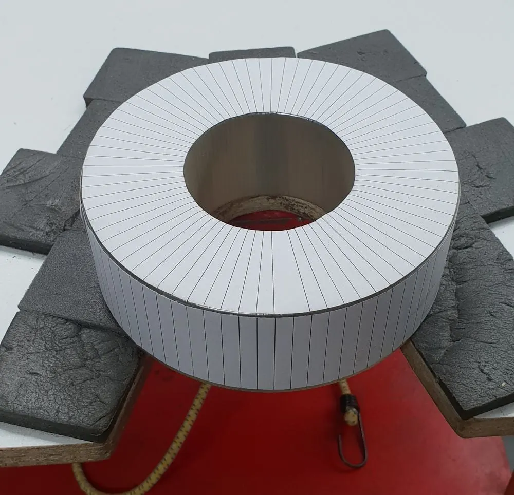
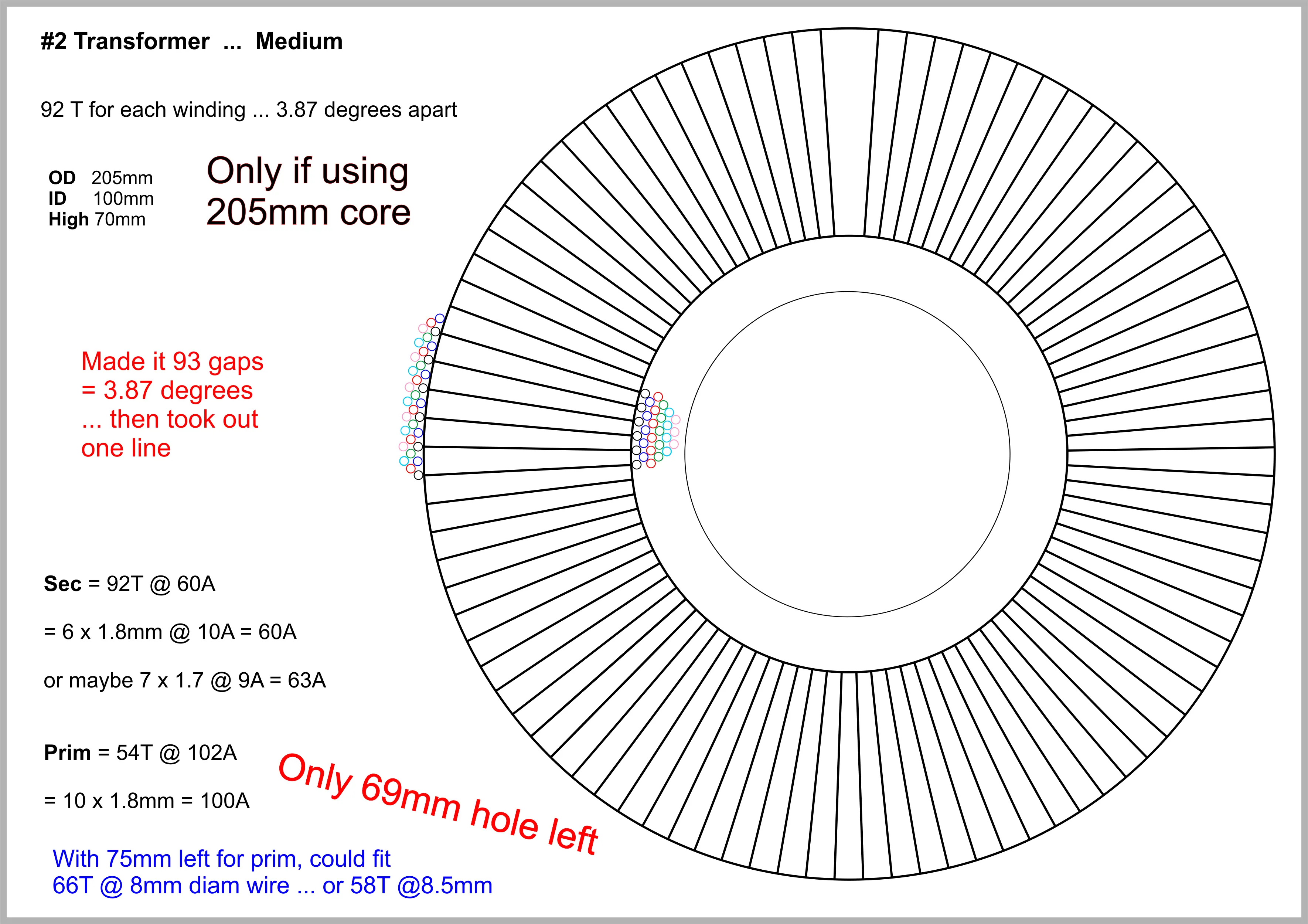
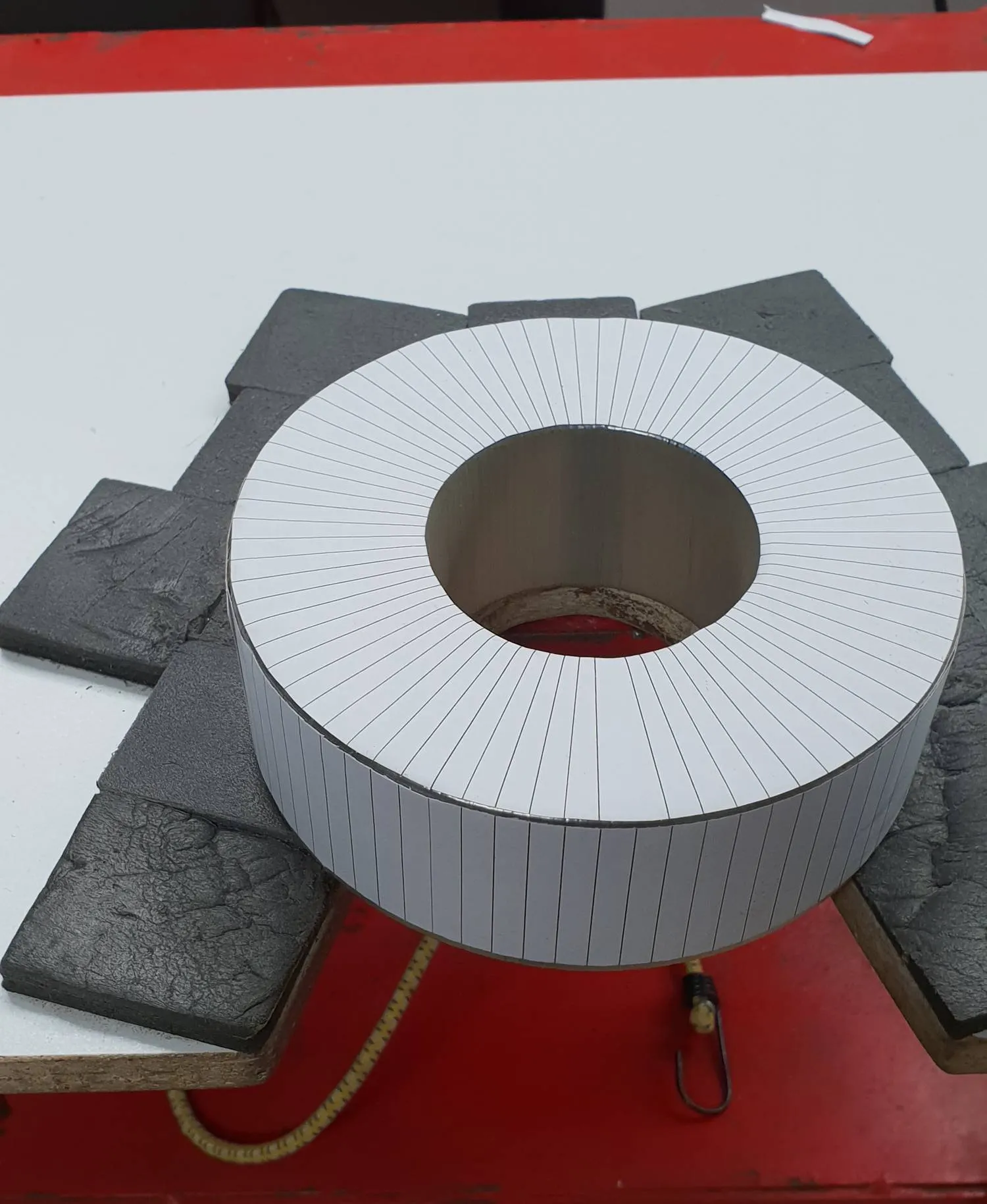
If you’re looking for a really neat and tidy wind, I found it helps to print a template so you know what spacing to use, to make your windings as neat as possible.

The neater and more consistent your first layer … the better, and quicker the subsequent windings will fall into place.

It may pay to wind mylar tape over each layer … to improve the insulation between layers … though that can reduce the hole size considerably, especially if there are a lot of layers.

If anyone has any questions, feel free to contact us and we can provide more information and add it here.

Some Random Photos

Click on photos to open enlarged versions

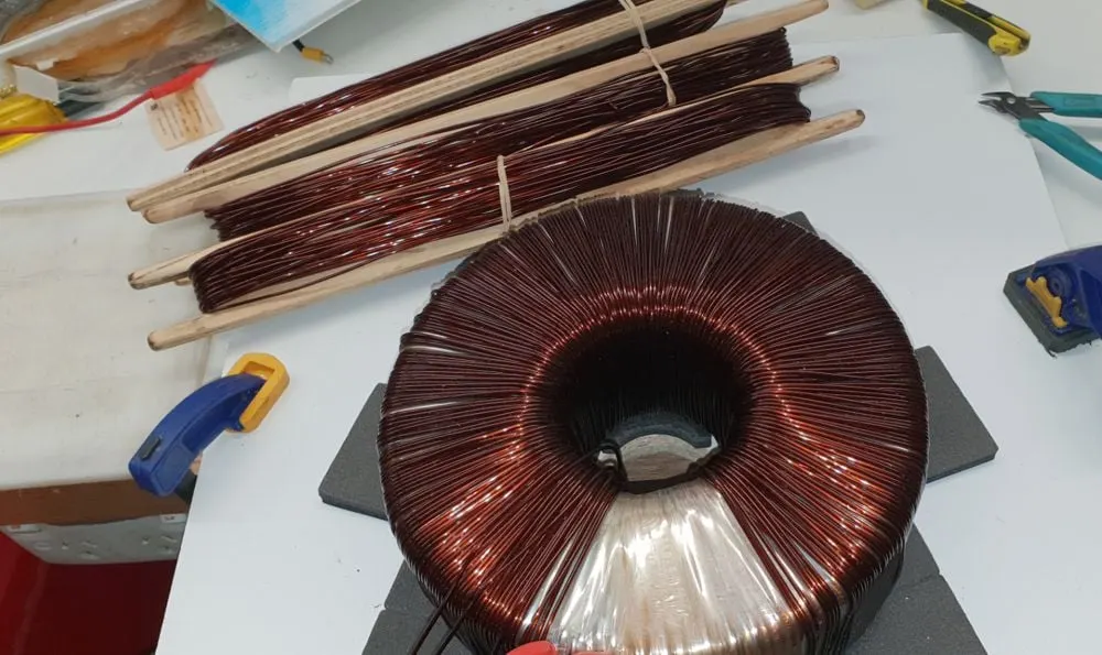
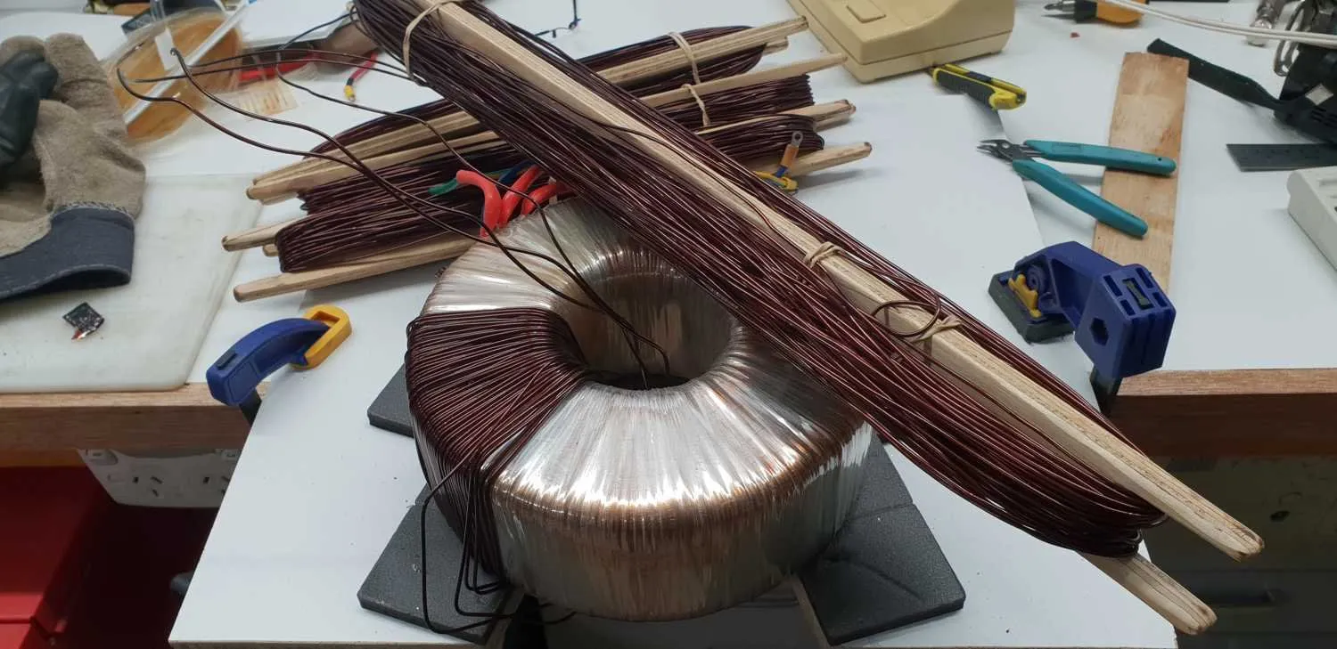
Several "shuttles" filled with wire while unwinding a toroid.

Keeps it manageable until have time to wind it off, stretch it out and straighten out any kinks. Then wind it up into larger diameter rolls until needed.

Cutting slot in hula hoop

A kids hula hoop is cut around the circumference for use as a winding tool.

The hoop is then cut so it can be fed through the toroid centre. A coupling is needed to hold the ends together again.

Can fit 20-30 turns inside ... 50 metres plus

This hoop's circumference was 2.105 metres ... and could fit more than 50 metres per fill.

Only just enough for some of the longer windings though.

With first layer positioned accurately, subsequent layers go on accurately and quickly

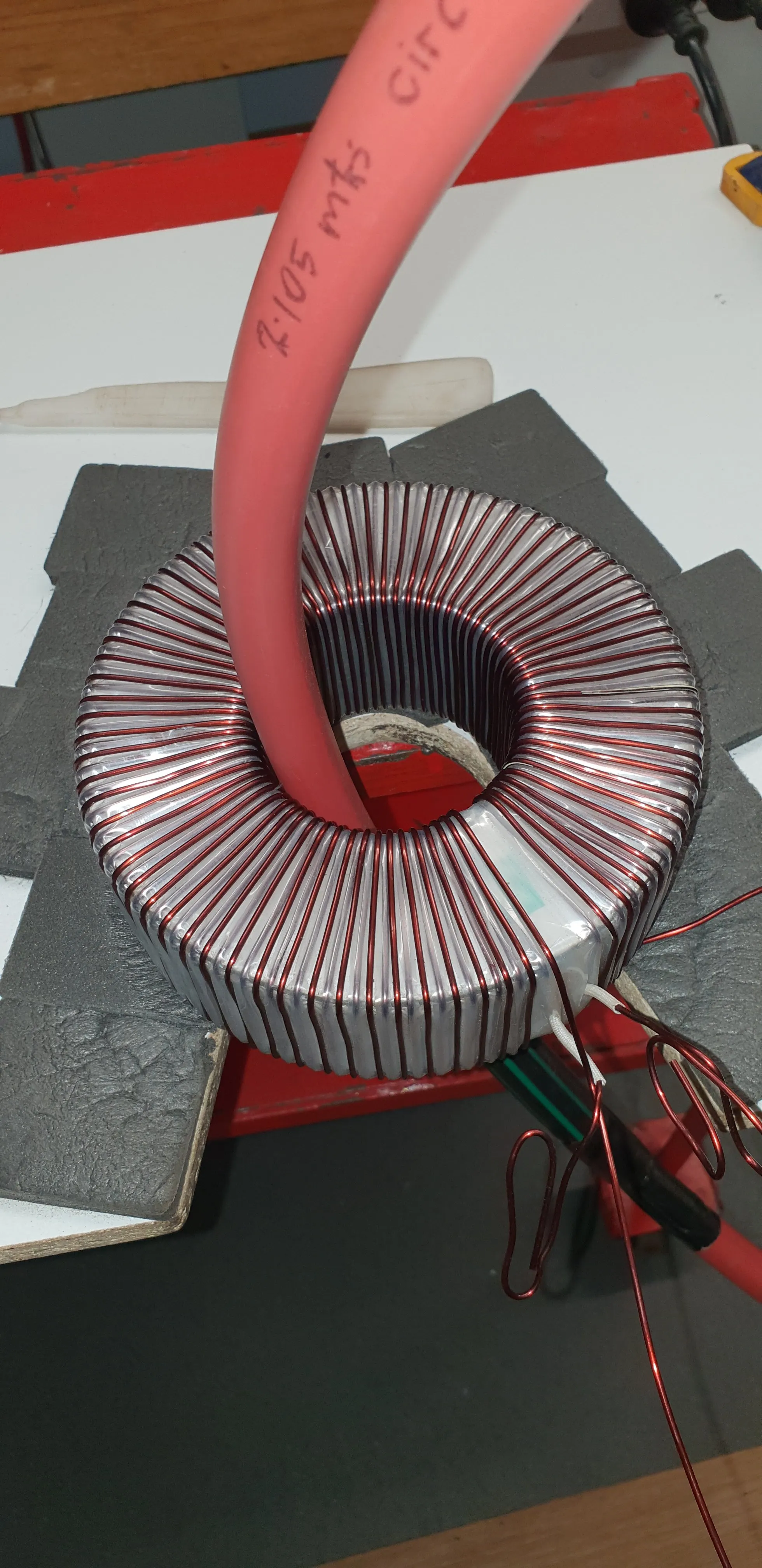
"2.105 mtrs" written on the hoop as a reminder.

The windings are very even and that's because the first layer was carefully spaced, so the next layer has no choice but to fit in the gaps of the first ... and can go on so much quicker.

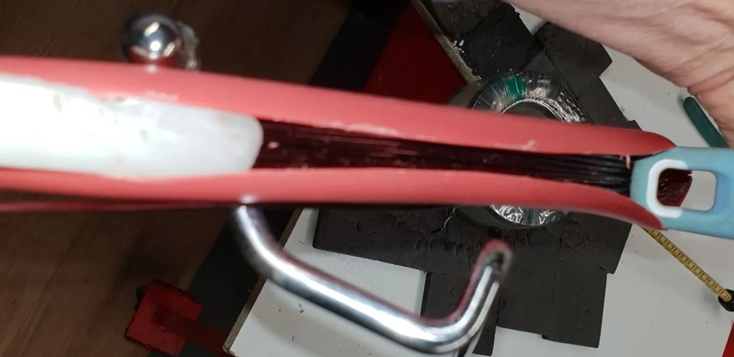
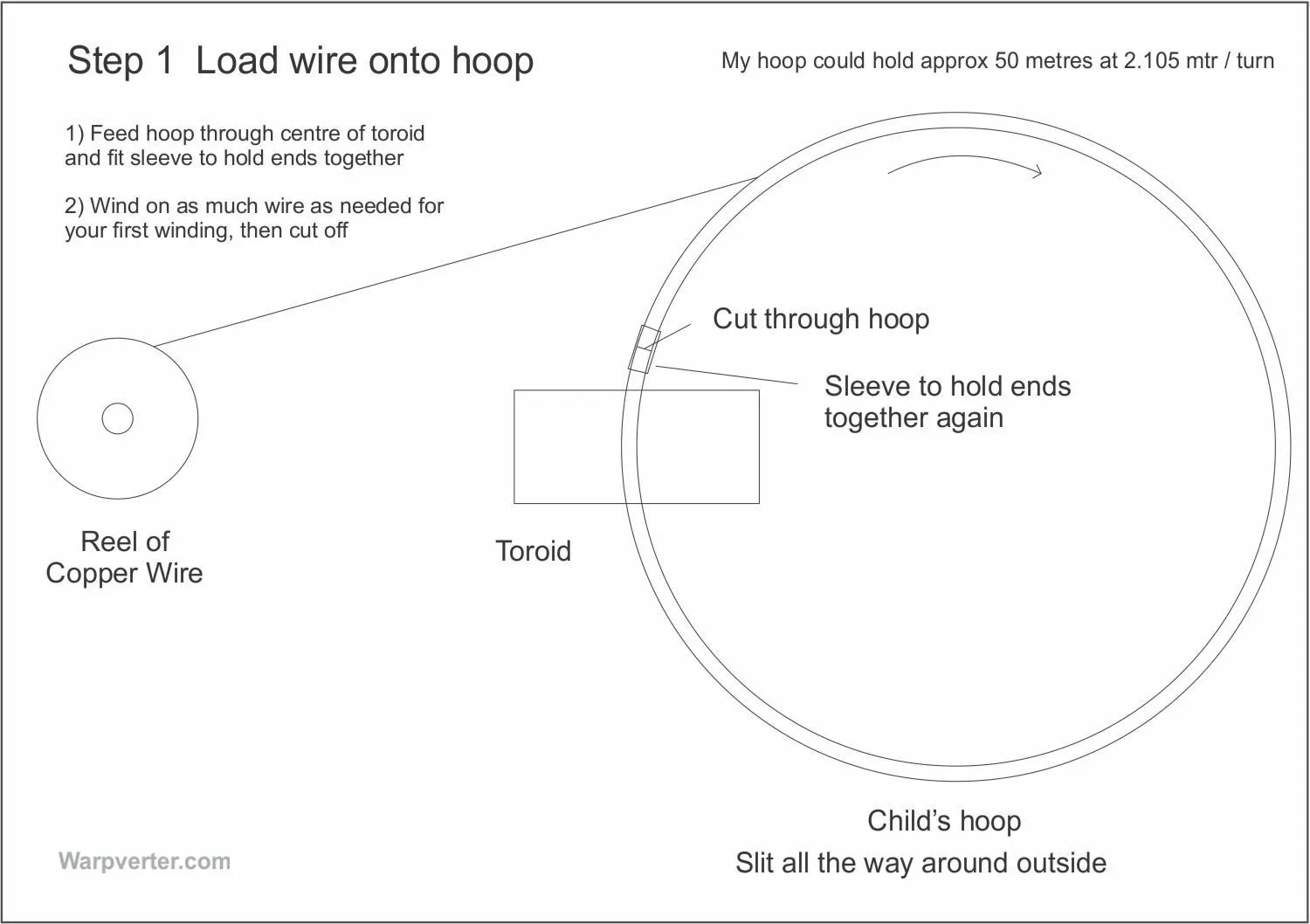
Load up wthe hoop with enough copper wire for the next layer

This illustrates the method of loading wire onto the hoop.

Click on it to see a large version or check the one at the bottom of the page.

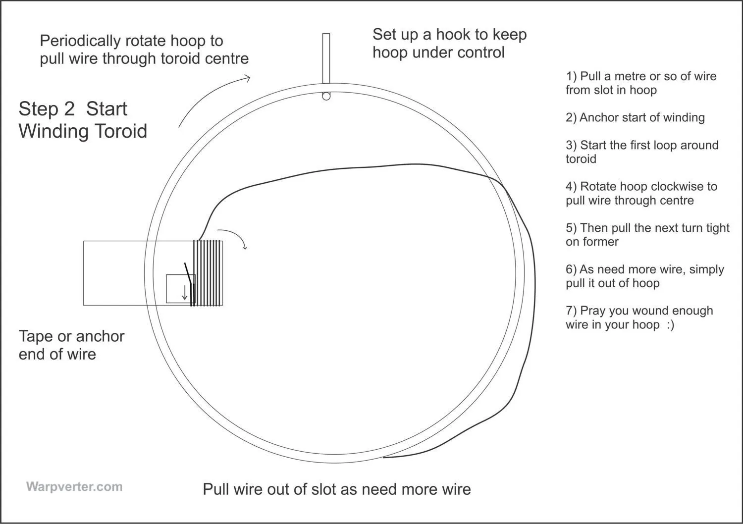
Start winding the toroid

And then start the winding process.

Once you understand how it's done it becomes an easy task ... maybe slow going, but certainly not difficult.

Use a template to space out the windings

I found that going to the effort of creating a template saved a lot of time winding and made for a very neat result.

Template created to make winding easier

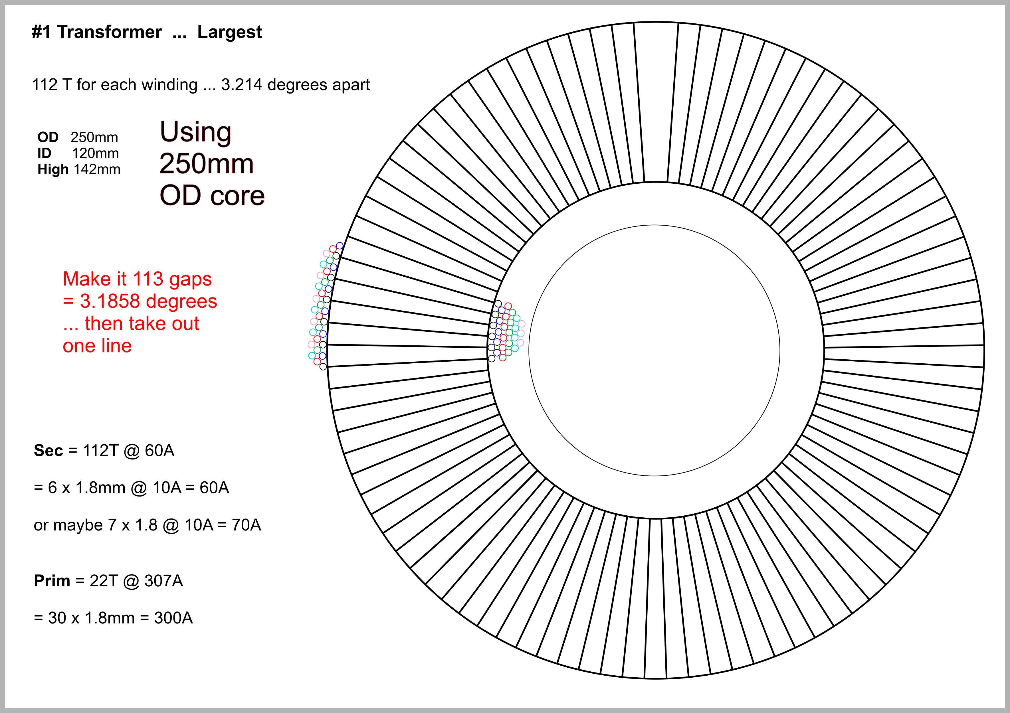
I used Corel Draw to draw a "star" with #Turns + 1 ... then removed one line from the print between the start and end of the winding.

Template for #2 Toroid

Template for the #2 "Medium" toroid

Super long shuttle

I used extra long shuttles as I wasn't going to cut the wire during unwinding.

Some toroids were wound with three wires at a time and became quite entangled.

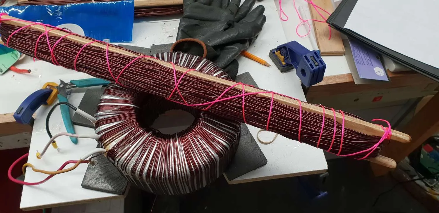
Bind the wire on the shuttle

Even then I had to bind the wire to keep it compact enough to feed through the centre.

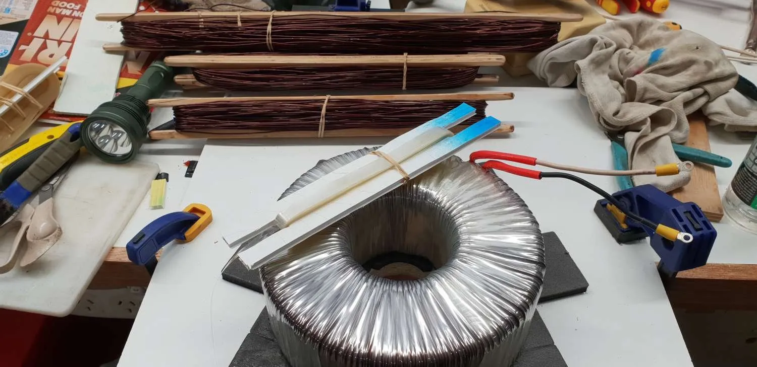
Mylar tape wrapped up on a cardboard shuttle

Mylar tape "de-wrinkled" with a hot air gun and wrapped on a cardboard shuttle, ready to be used on the new winding.

Building a Big Core

Click on photos to open enlarged versions

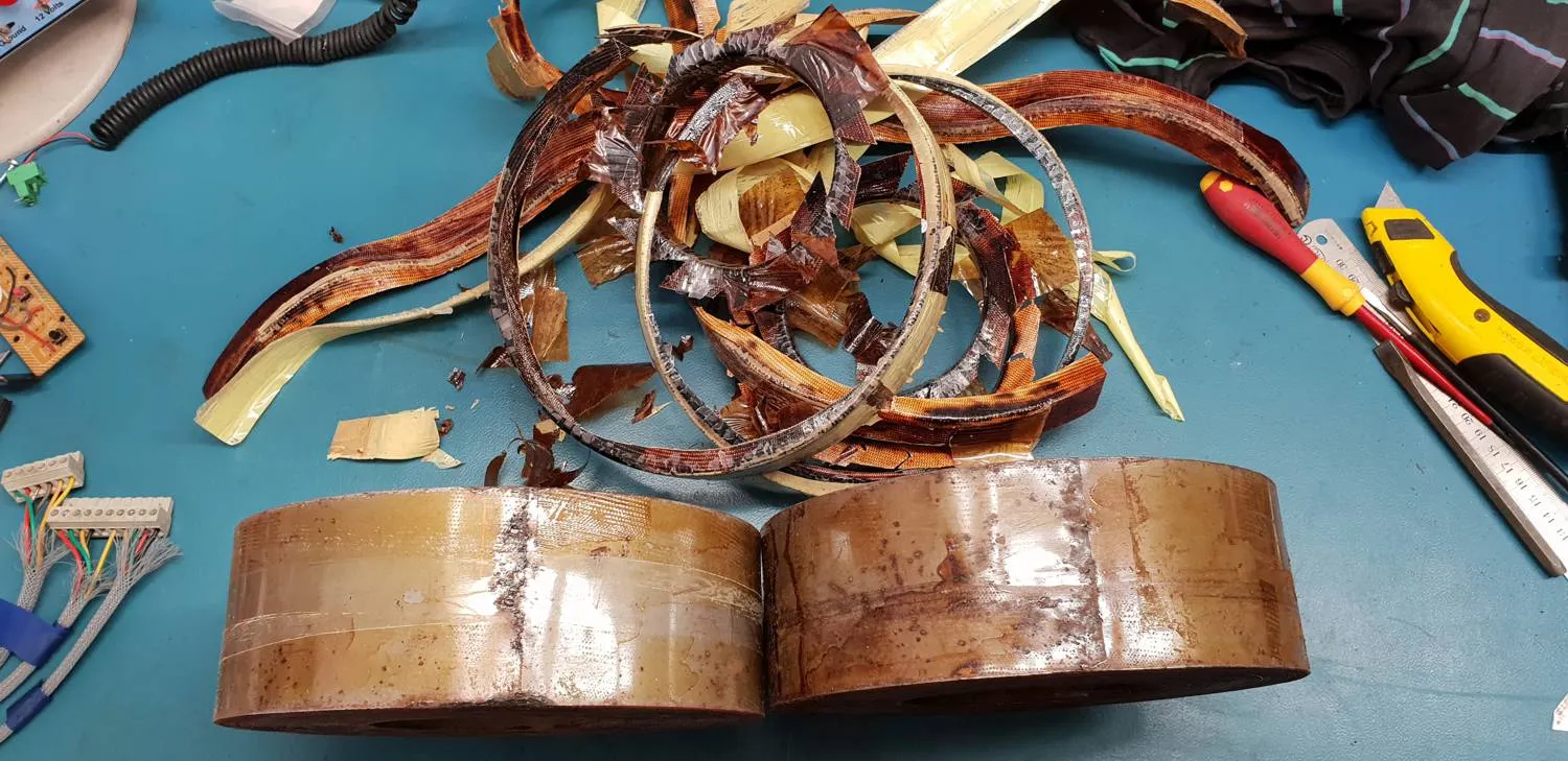
Stripped two 3kW Aerosharp toroids

Started by stripping four 3kW Aerosharp toroid cores  ...
two to build onto and two sacrificial cores to add to the first.

Removed 20mm from the ID

Then removed 20mm from the inside diameter of each to allow enough room for the planned windings ... especially the 75mm squared 300 amp primary winding.

Homemade core winder

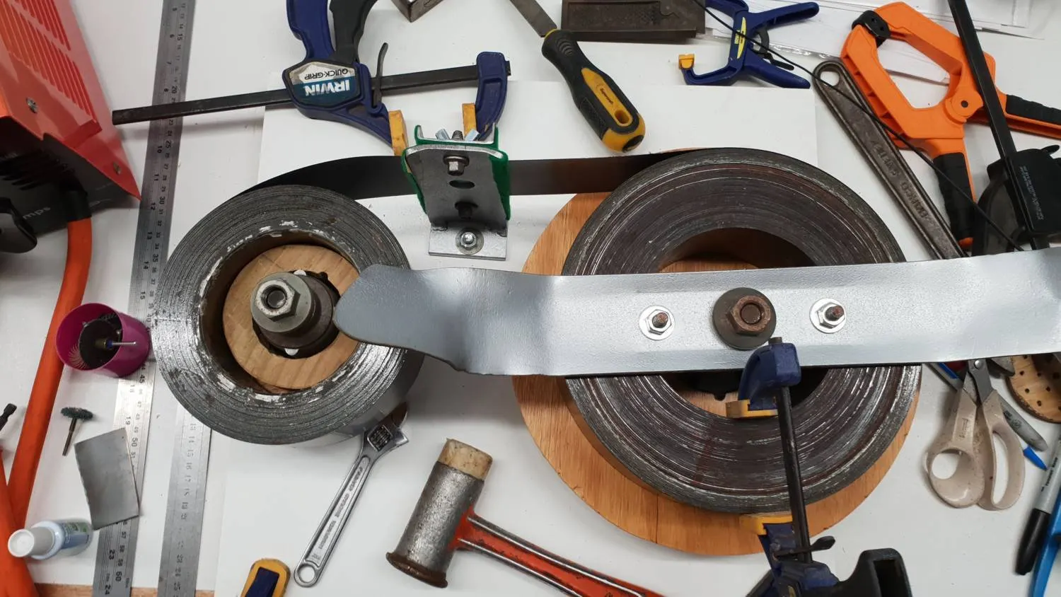
Built a core winder to build up the outside diameter with spindles and felted post all under tension so the core remained tight.

All old parts from my ride-on mower after changing the blade spindles. Even used an old blade.

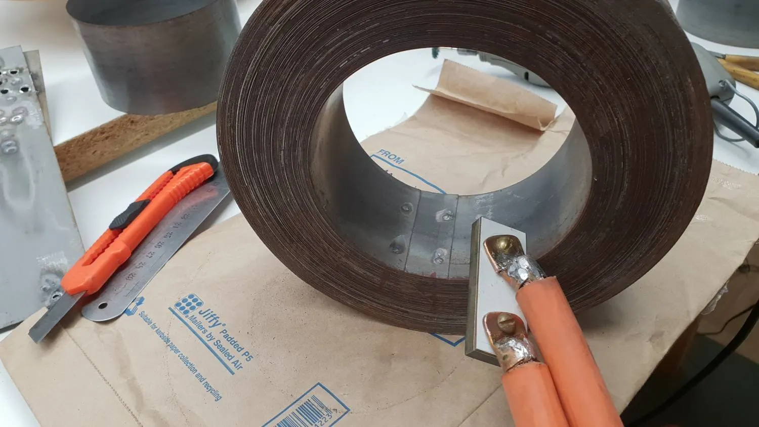
Spot welded the core to prevent unraveling

Spot welded the core to prevent it unravelling. Overkill really because tape and superglue would have worked.

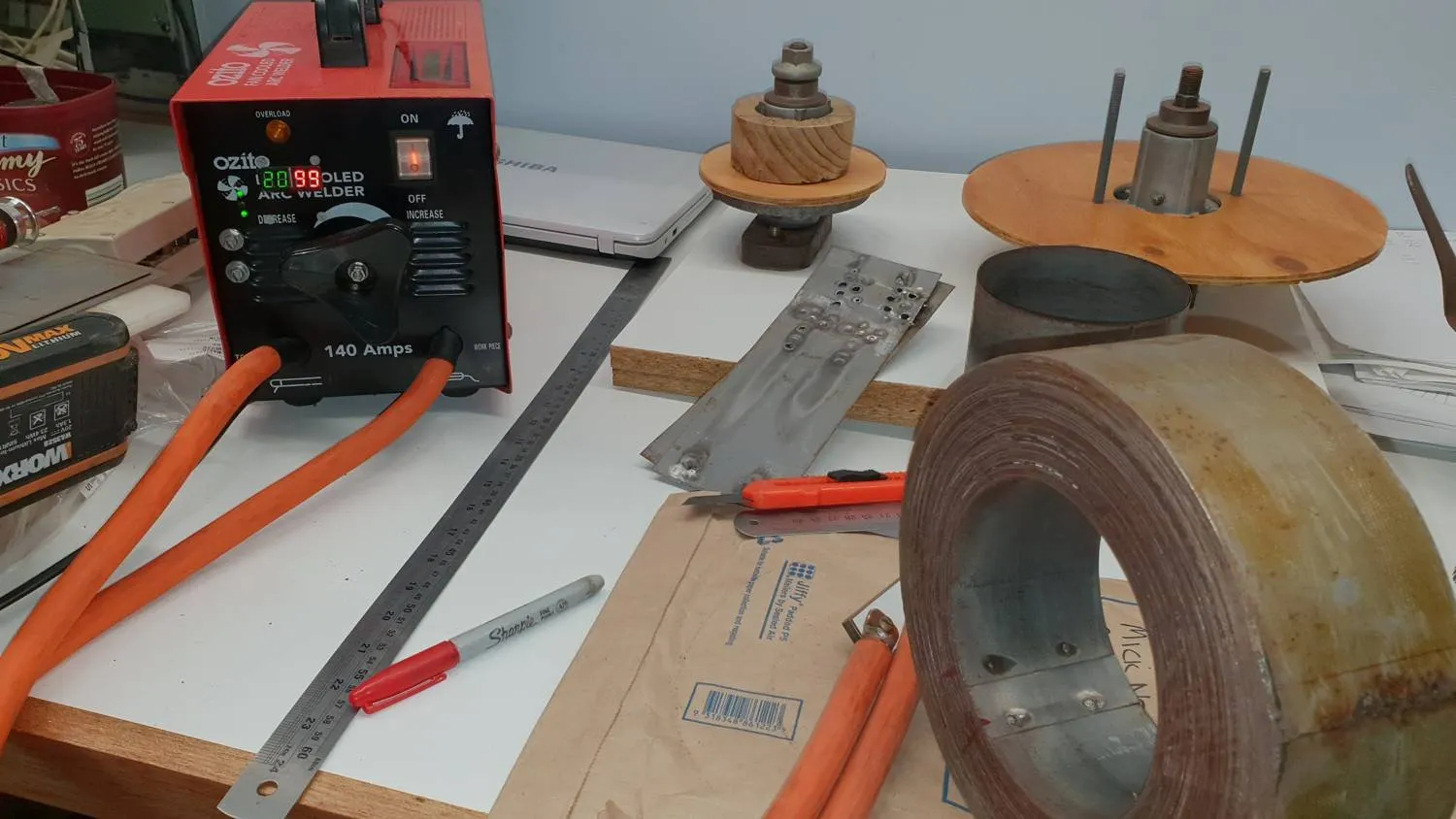
Home made spot welder by converting and old stick welder

Of course I had to build the spot welder first, by converting an old stick welder.

My first attempt with an old microwave oven transformer wasn't powerful enough.

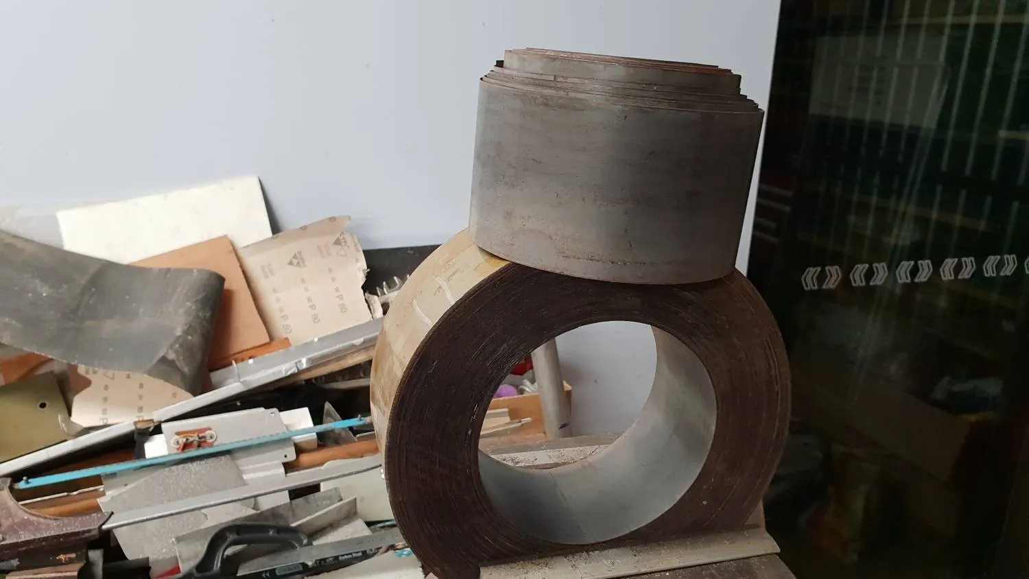
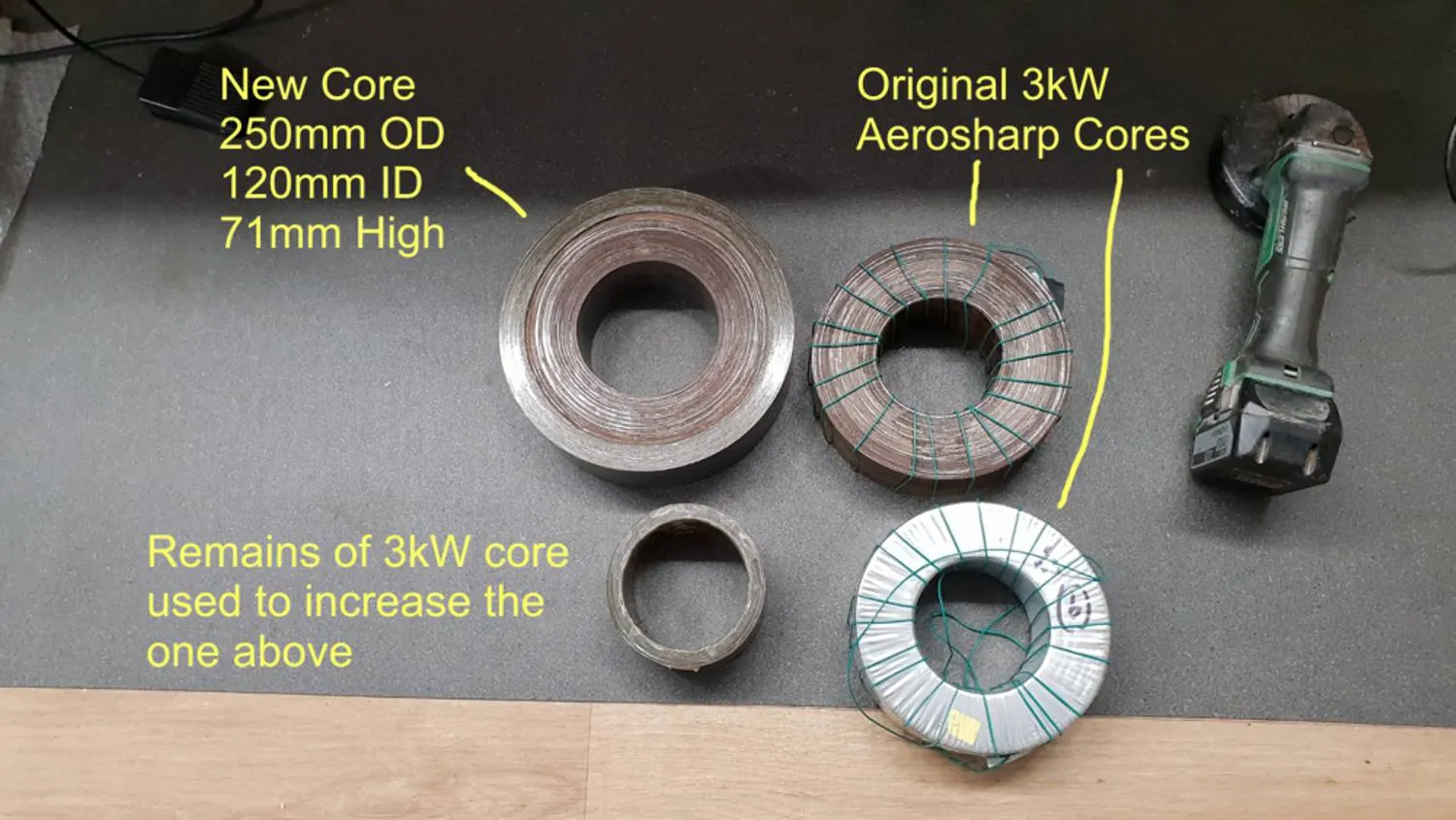
All 3kW Aerosharp toroid cores in various states

Both cores on RHS are 3kW cores.
Top left had 20mm removed from ID and 50mm added to OD to become 250mm OD
Bottom left is all that remains of a full 3kW core after adding to the top left one!!!

Two new big cores stacked together

Then I wound a second one and stacked the two.

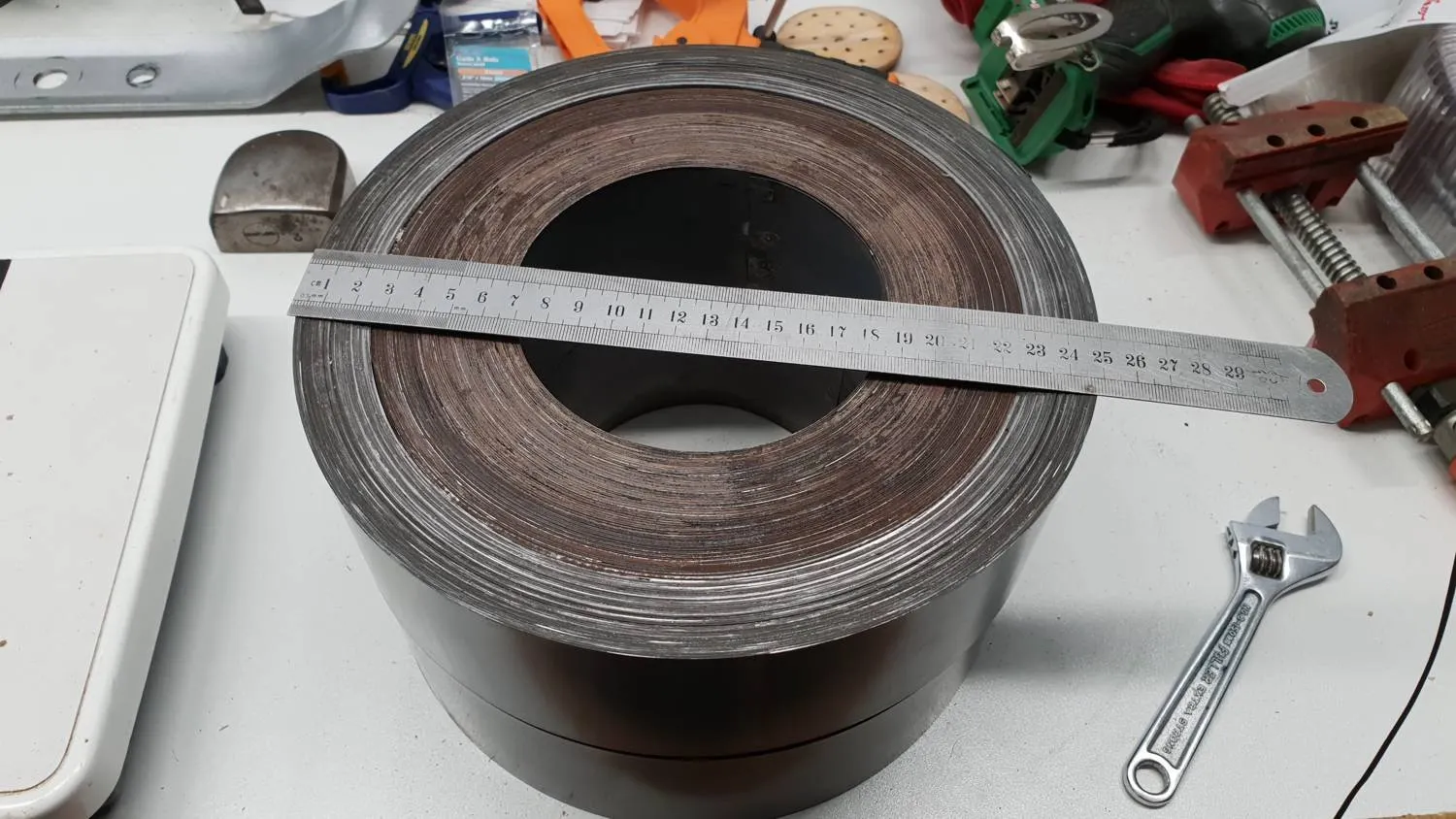
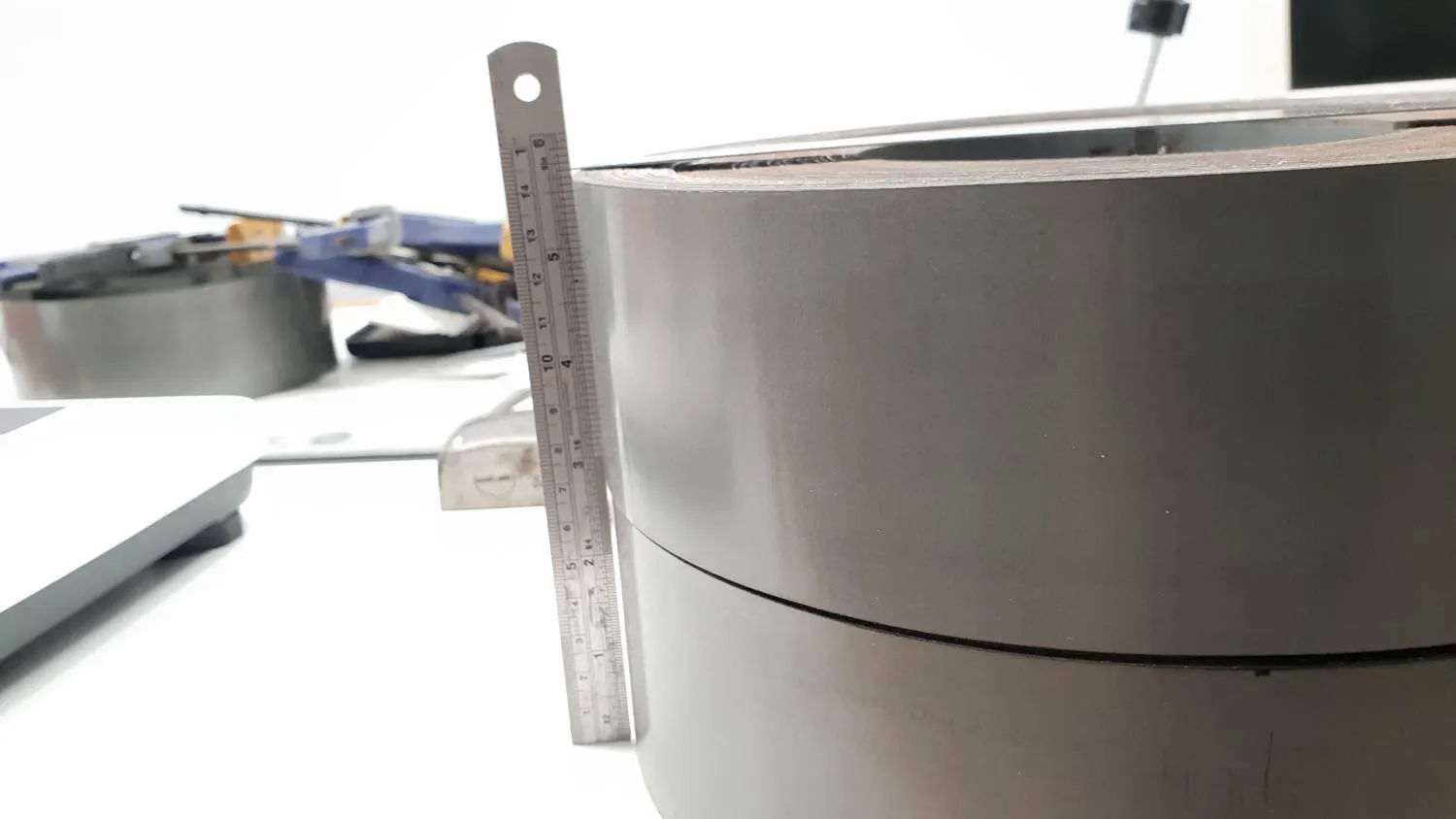
Two enlarged cores stacked

142mm high, 250mm outside diameter and 120mm inside diameter.

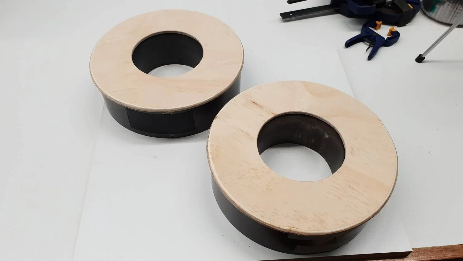
two plywood end caps prepared

Plywood end caps made to space the first winding away from the core  ...  and provide rounded edges to protect the wire as it was wound.

Centre insulator

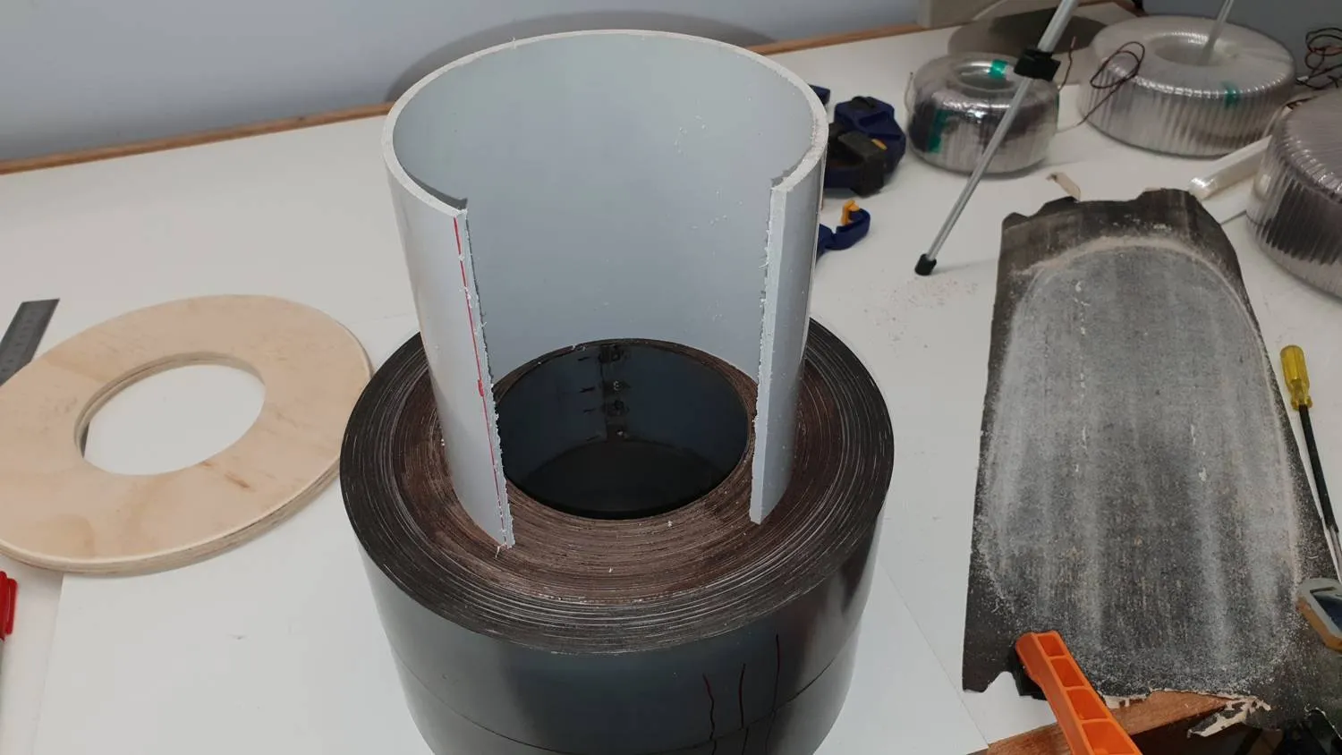
A piece of pvc pipe was cut to slide down the centre to provide insulation and keep the cores and the end "washers" centred.

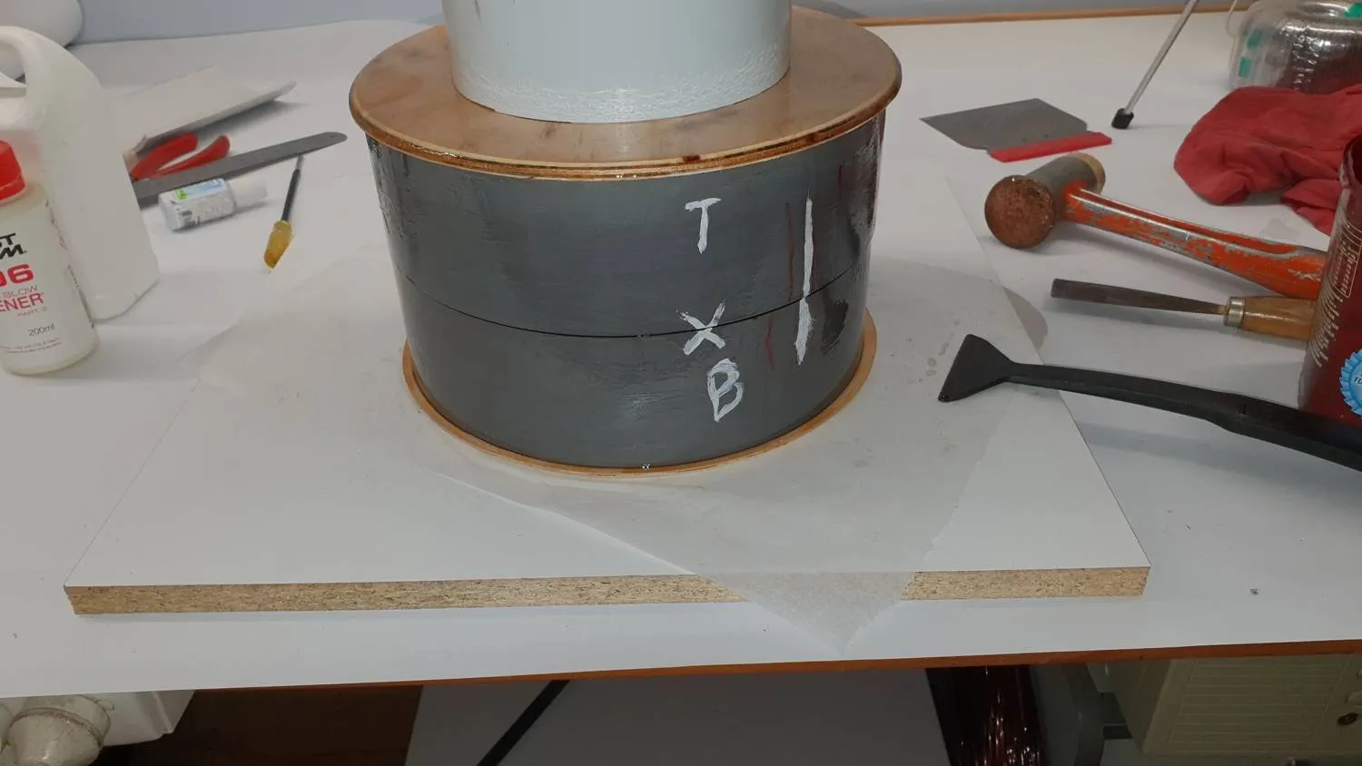
All epoxied together and waiting to dry (with weight on top)

All epoxied together with weight on top and waiting to dry.

I also poured a heap of superglue into the cores beforehand to keep them bound up and try to prevent any rattling in the future.

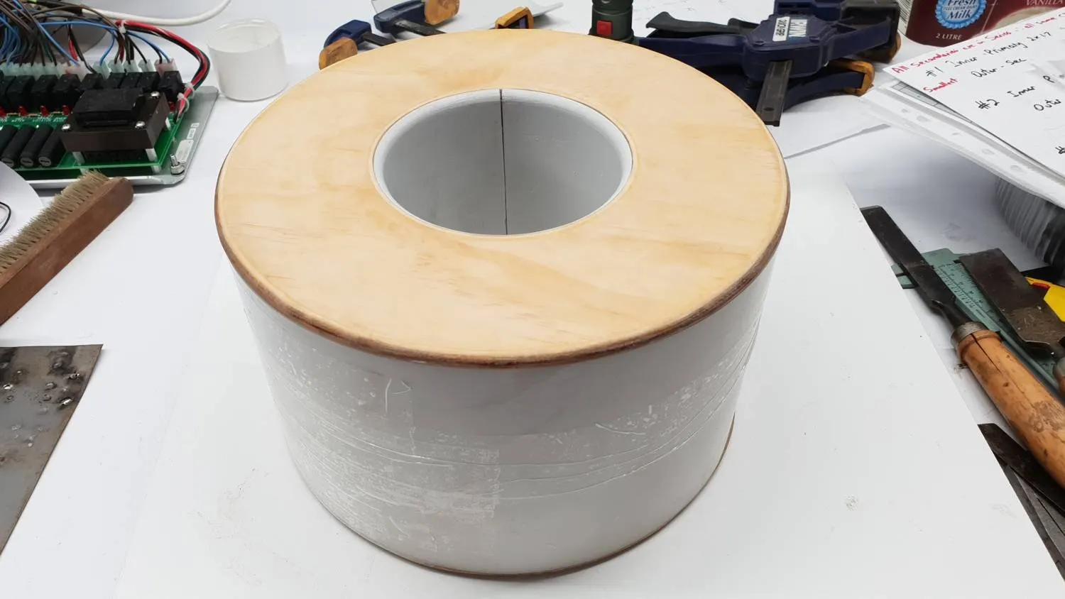
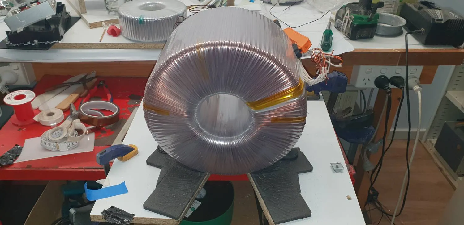
Large core all complete and insulated

#1 Core all complete and insulated, almost ready for winding.

Oh, and around 40kg at this stage.

Grooved the edges ready to locate the windings

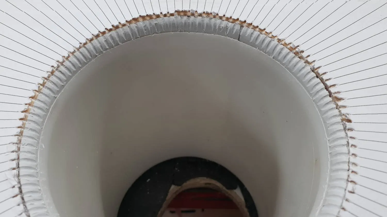
Printed a template to show me where to space the wires ... then grooved the corners to locate each winding.

I can't emphasize enough how much that step helped in the overall winding of this toroid.

I used templates for two of the other toroids as well

I printed templates for all toroids after I wound the first one and being uncertain of the spacing and having to regularly re-count the numbr of turns. Worked very well.

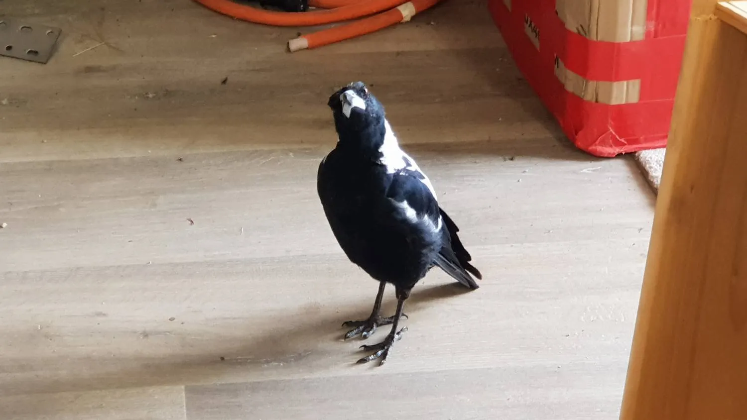
Inquisitive visitor

An inquisitive visitor : )

What on earth are you building there man?

Winding the Big Core

Click on photos to open enlarged versions

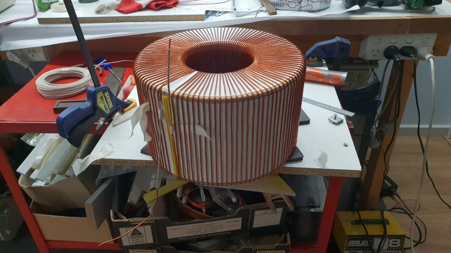
#1 Tx first layer wound

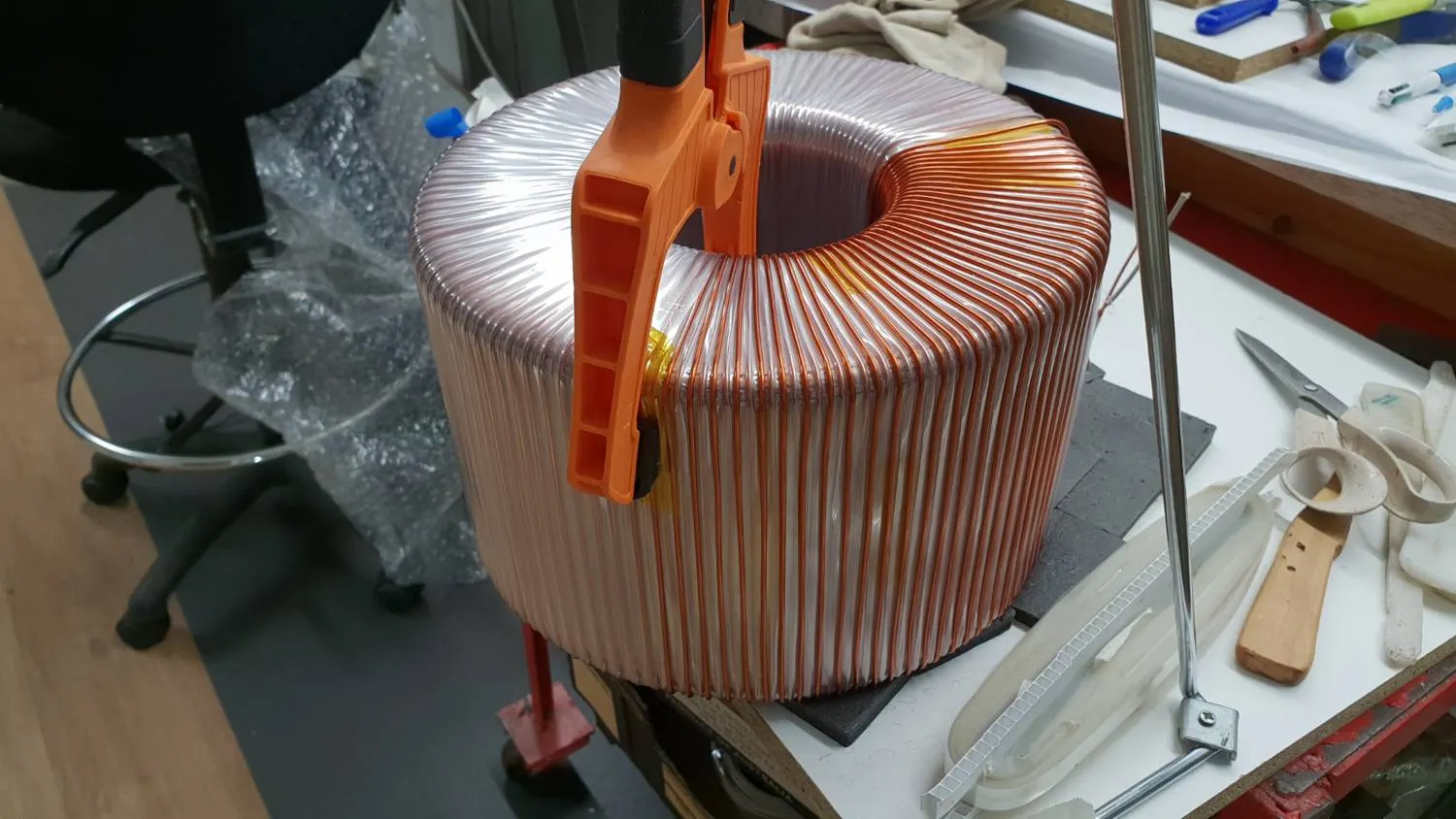
#1 Tx first layer of six complete.
112T / layer

Insulating with mylar tape

Insulating with mylar tape saved when unwinding the Aerosharp cores.

Large clamp was very handy to hold it in place when I needed a break or to join more on.

Afew layers later

A few layers later and that inside hole is getting lots smaller. 

Need a fair bit of room yet for the 300 amp primary winding.

Final layers of mylar added to #1 Toroid

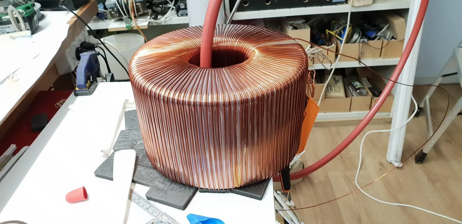
Final layers of Mylar and ready for the primary winding.

First windings complete on all four toroids

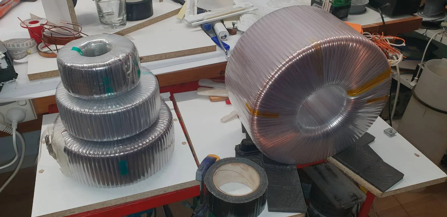
That's the main windings done on all four toroids  ...  now just need the primary windings on #1 and #2  ...  and the secondary windings on #3 and #4

#1Tx primary winding complete

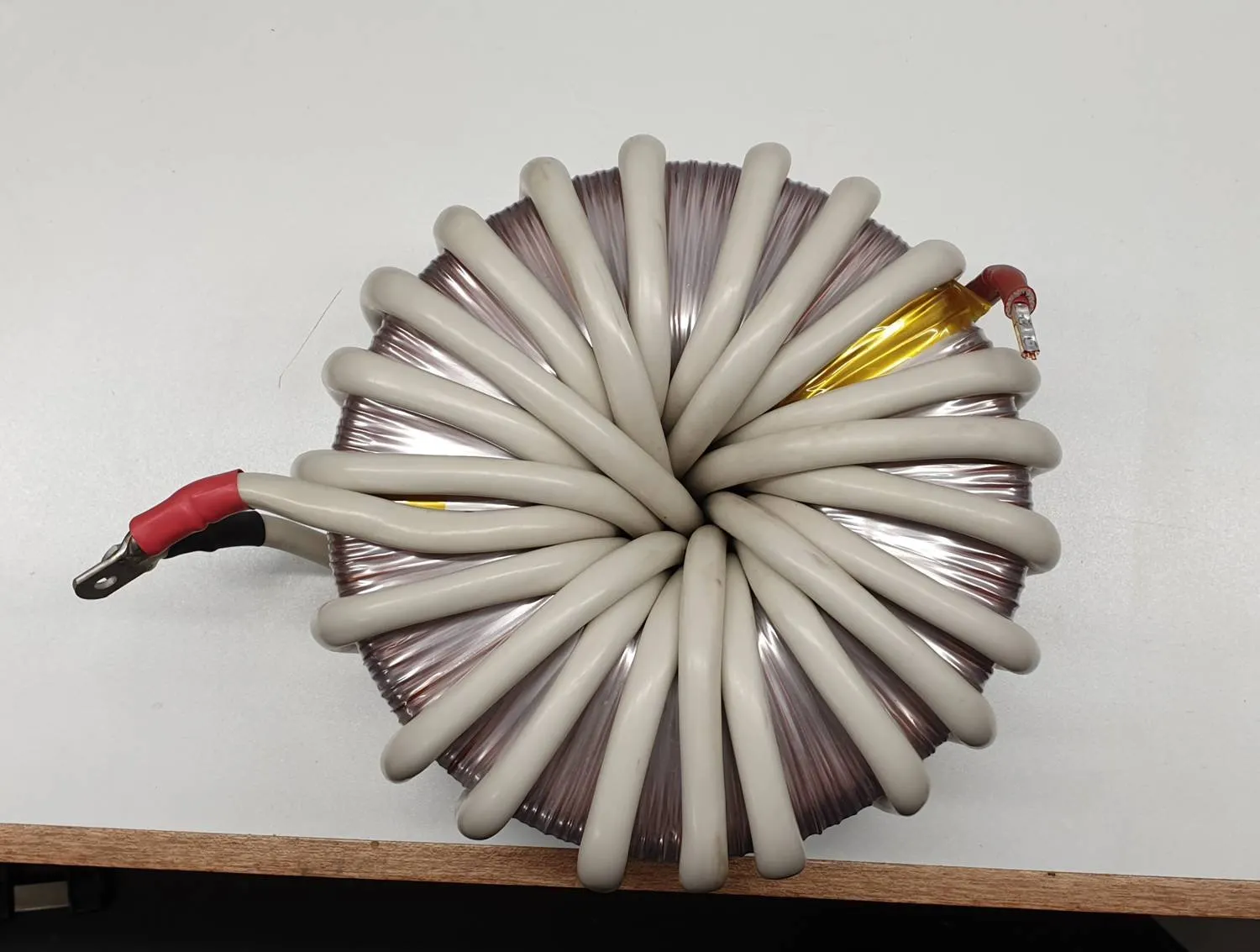
#1 Toroid complete with 22 turns of 75mm welding cable for the primary.

Backtracking to Add Shielding

Click on photos to open enlarged versions

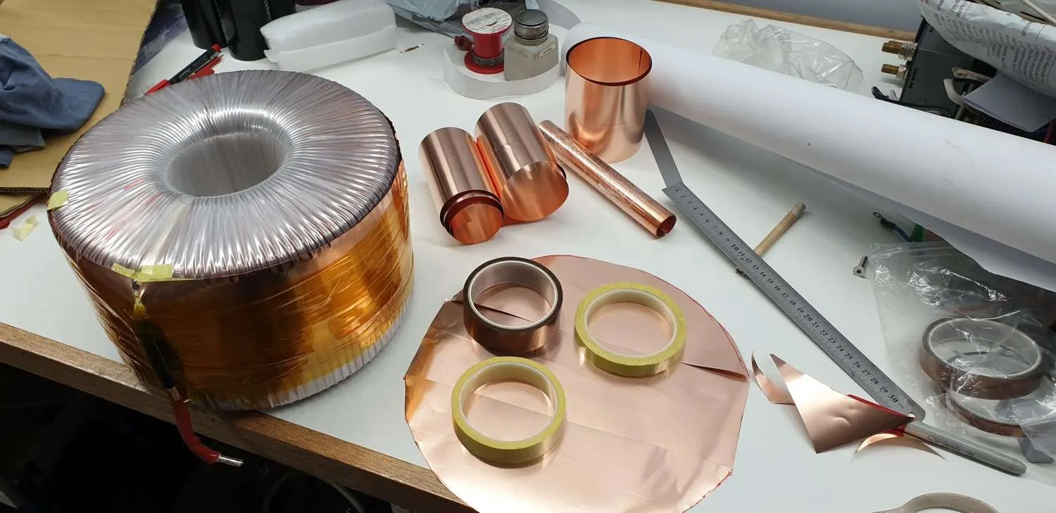
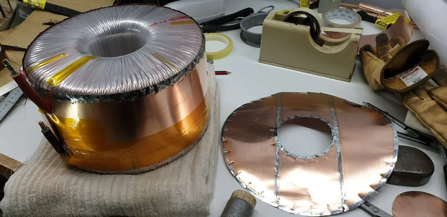
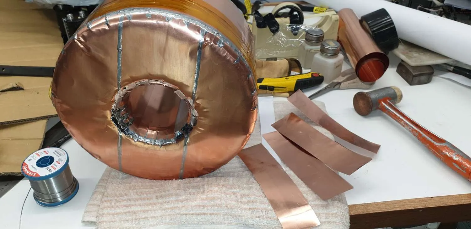
Starting to wrap #1Tx in copper foil

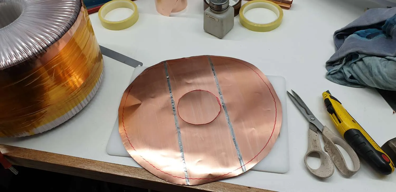
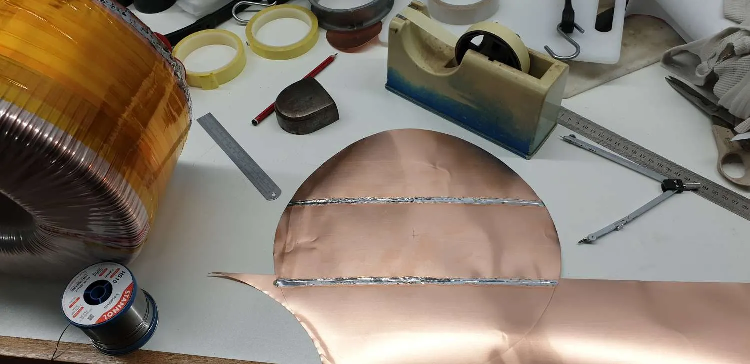
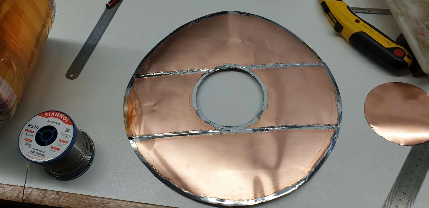
Had to solder three strips together to cover the width.

Making an end cap

Being clean and shiny made it easy to tin and sweat together.

A second end cap

And avoid waste : )

Cutting it out

Turned out to be a lot easier to tin the joining surfaces before soldering them together.

Tin the edges

Made lots of cuts into the edges to help with the bending process.

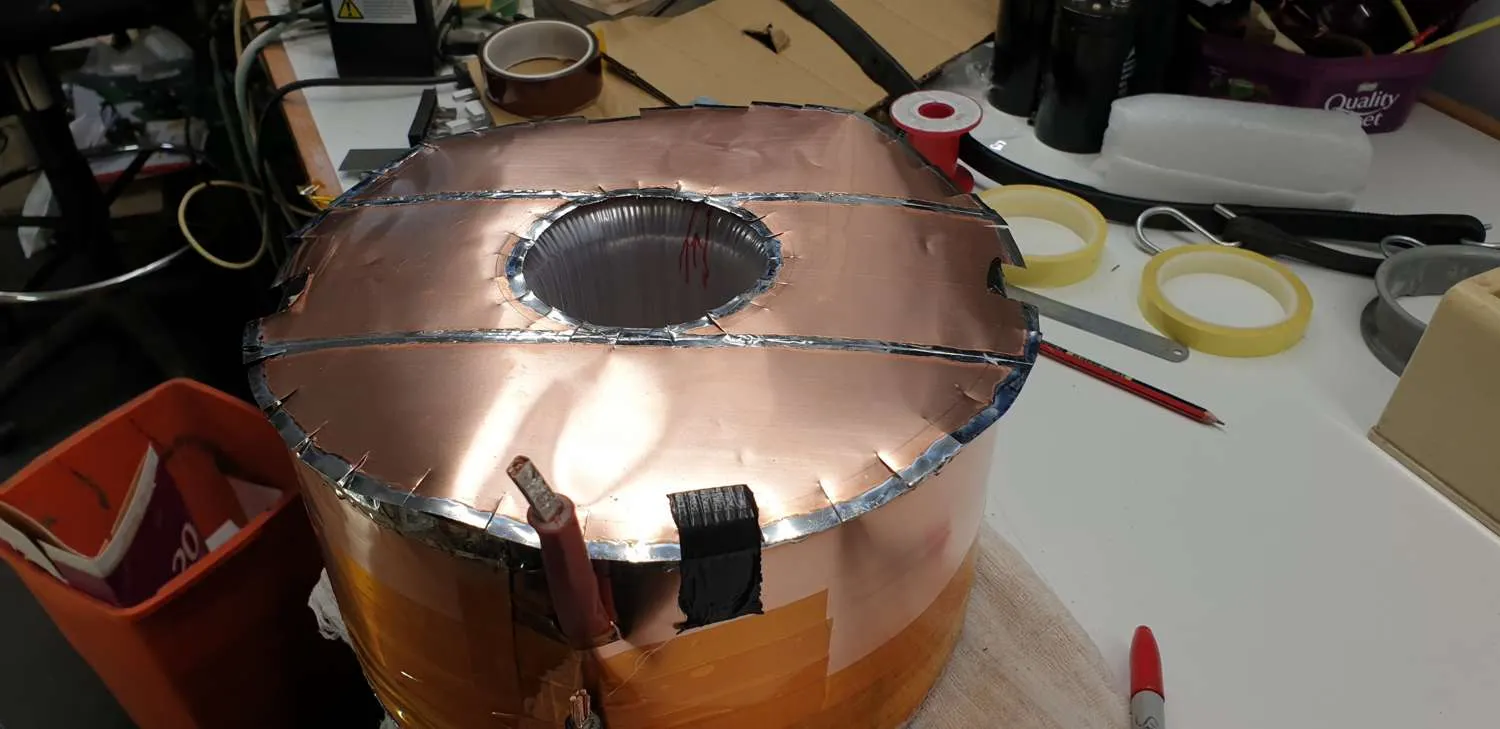
Ataching the end cap

Taped the 'lid' on and worked at curving the edges to create smooth joins.

Stitching it on

I'll never be a panel beater but this worked well enough

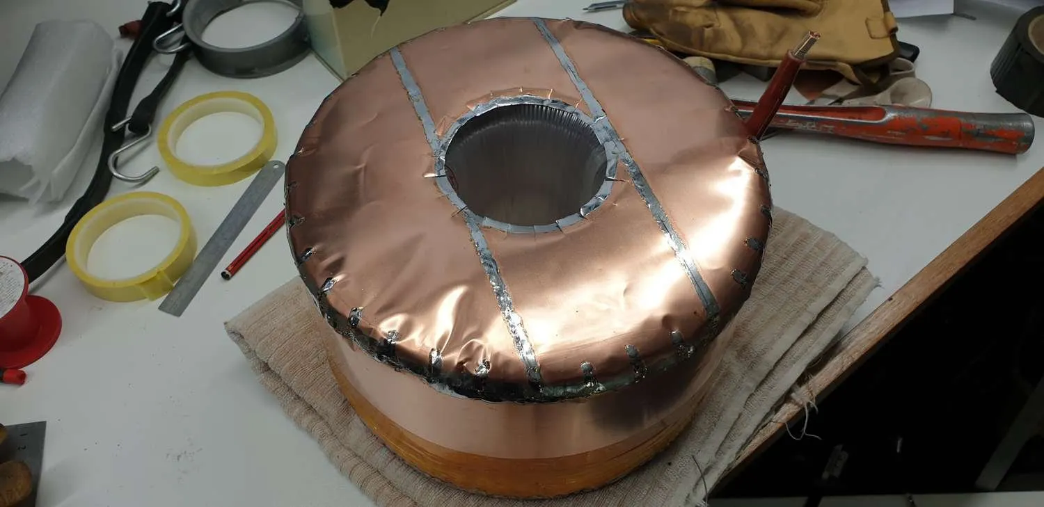
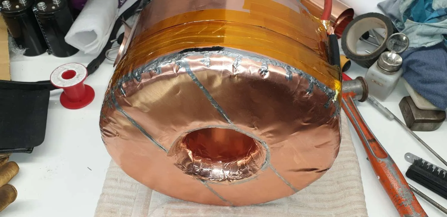
Solderng it on

The centre was filled in with strips though would have been nice to roll a piece around.

All covered in copper foil

The foil was .1mm thick and quite solid and I used some much thinner and flexible adhesive copper foil to cover up the rough areas and make it look nicer.

DF-8  ...  A Time Saving Tool

Click on photos to open enlarged versions

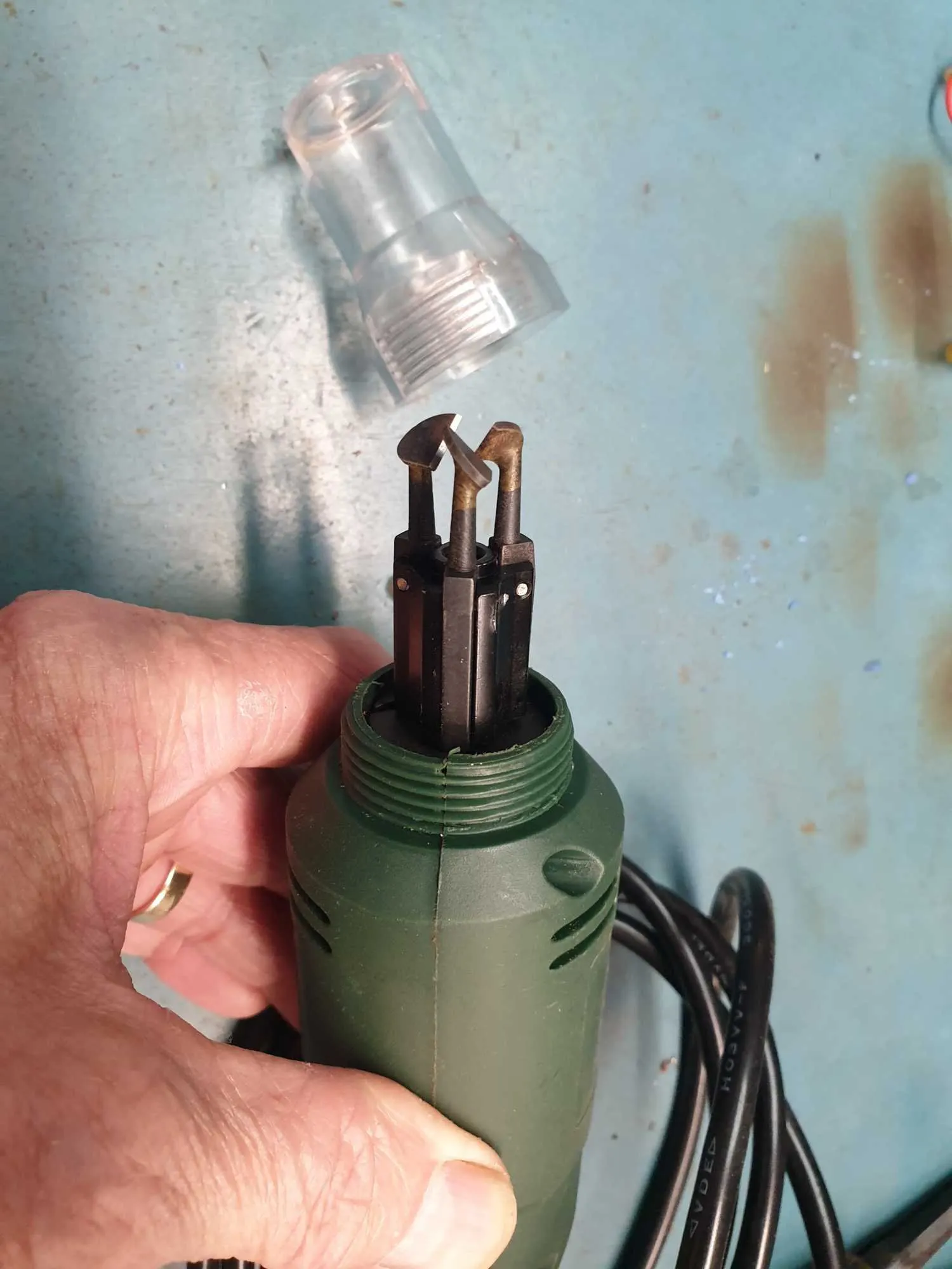
DF-8 Enamelled Wire Stripper

The arms are pivoted lower down with counterweights on the other end.

When spun, the centifugal force on the other ends force the blades in towards the wire and scrape off the enamel.

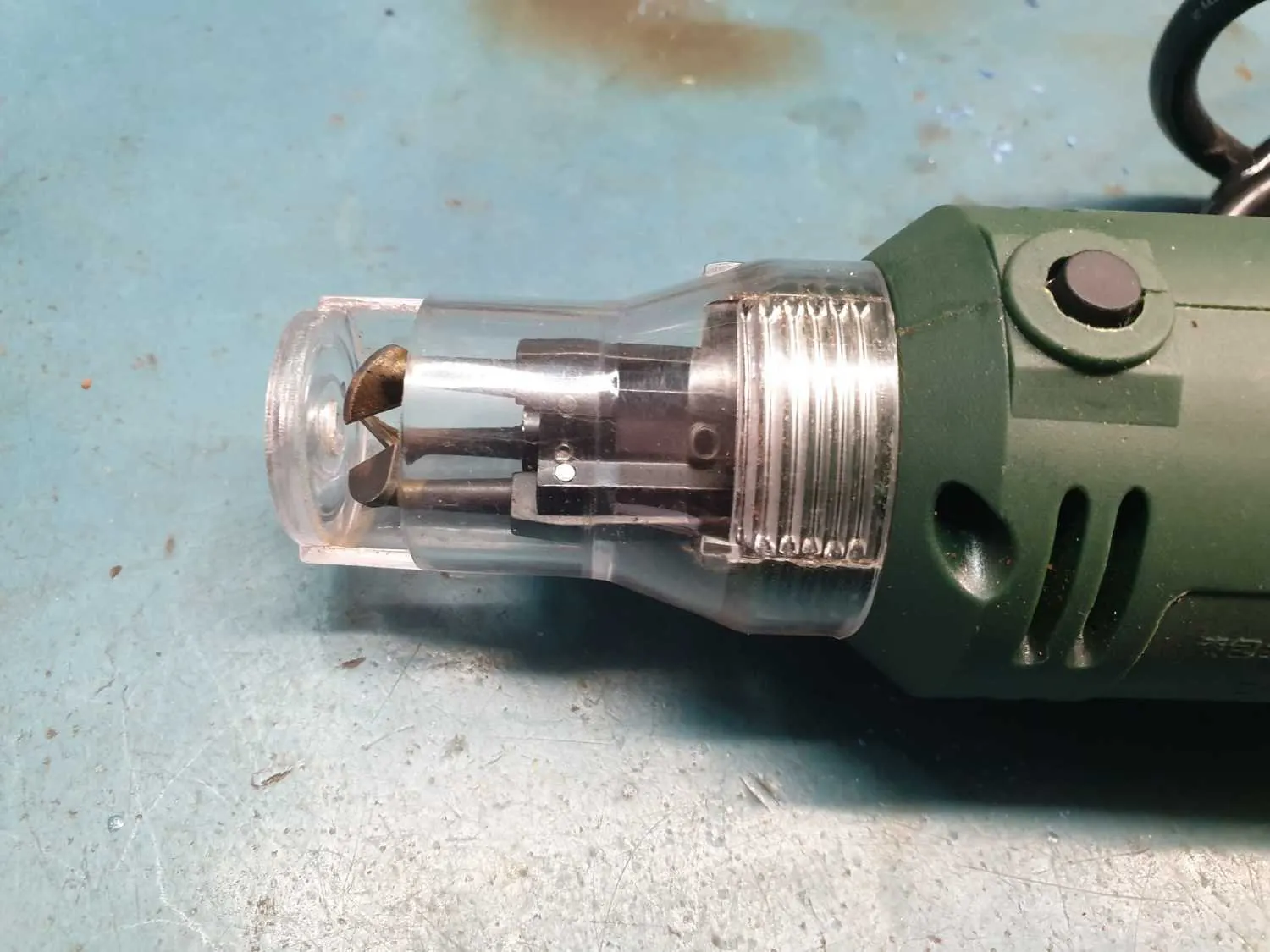
DF-8 enamelled wire stripper with protective cover

It is normally operated with the cover on.

Very Useful DF-8 Enamelled Wire Stripper

A great investment if you use a lot of enamelled wire in your projects.

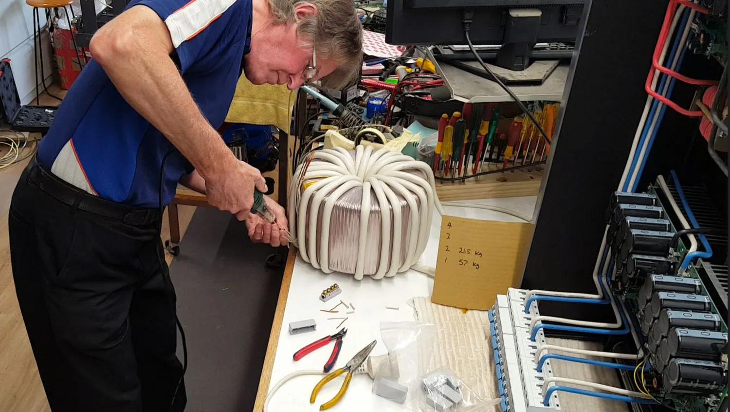
Using the DF-8 on the large toroid

There were 6 wires to be stripped on each end of the secondary and this sure speeds it up.

DF-8 enamelled wire stripper with protective cover

I even had an expert on the job from time to time.

And super happy to have the wire stripper to terminate each end.

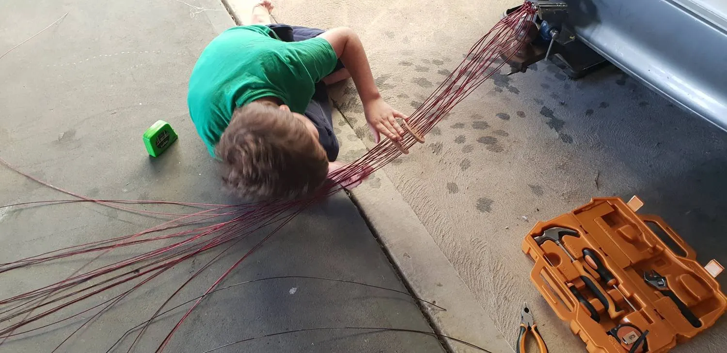
Anchored it to the tow bar

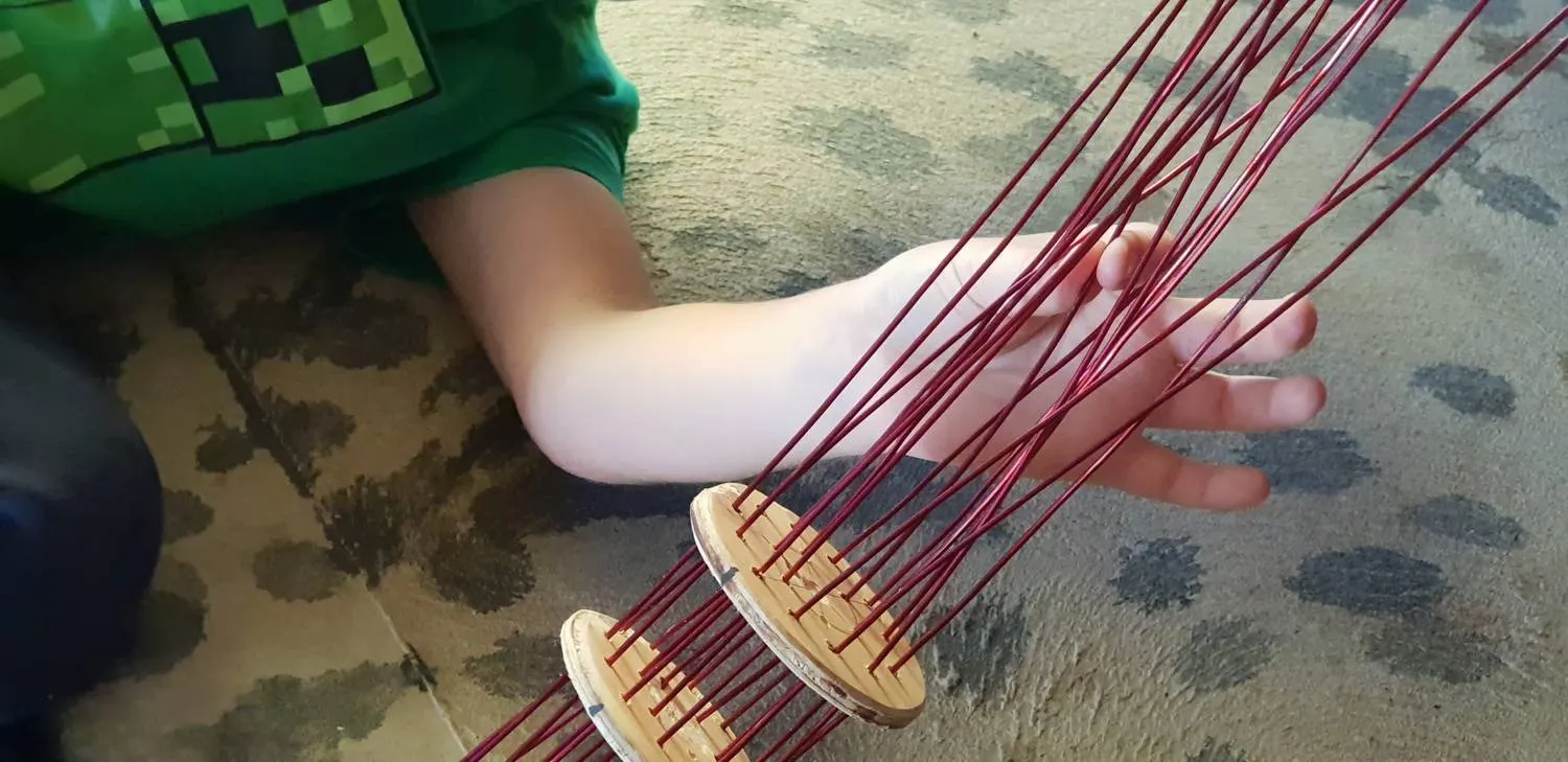
I needed some help threading the wire through the spacers.

The spacers kept the wire in order and lined up while it was being wrapped.

The first step is to load the reel with the length of wire you need.

Loading the reel with copper wire

The second step is to wind the toroid.

Picture what happens when you rotate the hoop clockwise ... it virtually winds itself. : )

And when you run out of wire, peel some more out of the hoop.

Start winding the toroid

Contact: Visit this thread on diysolarforum and message Warpspeed or rogerdw  

Waveforms

© 2024 Warpverter.com - All Rights Reserved.   Terms of Service:  Privacy Policy