Warpverter
A Serious Electronic Project For The Expert DIYer
Roger's Build
My journey started when trying to understand why normal grid tie inverters couldn’t be adapted to work off grid.
After a short time on the fairly hostile Whirlpool forum I was invited over to thebackshed forum where I was awakened to a whole new world of do it yourself inverters with the OzInverter and variations of the theme.
After months of reading through the threads and learning who knew what they were talking about … and who didn’t … I got wind of Warpspeed’s homebuilt StepInverter and fell in love with the idea of building one.
My biggest hesitancy was that it required four toroidal transformers to be wound as against just one for an OzInverter ... and I really struggled with the thought of winding even one!
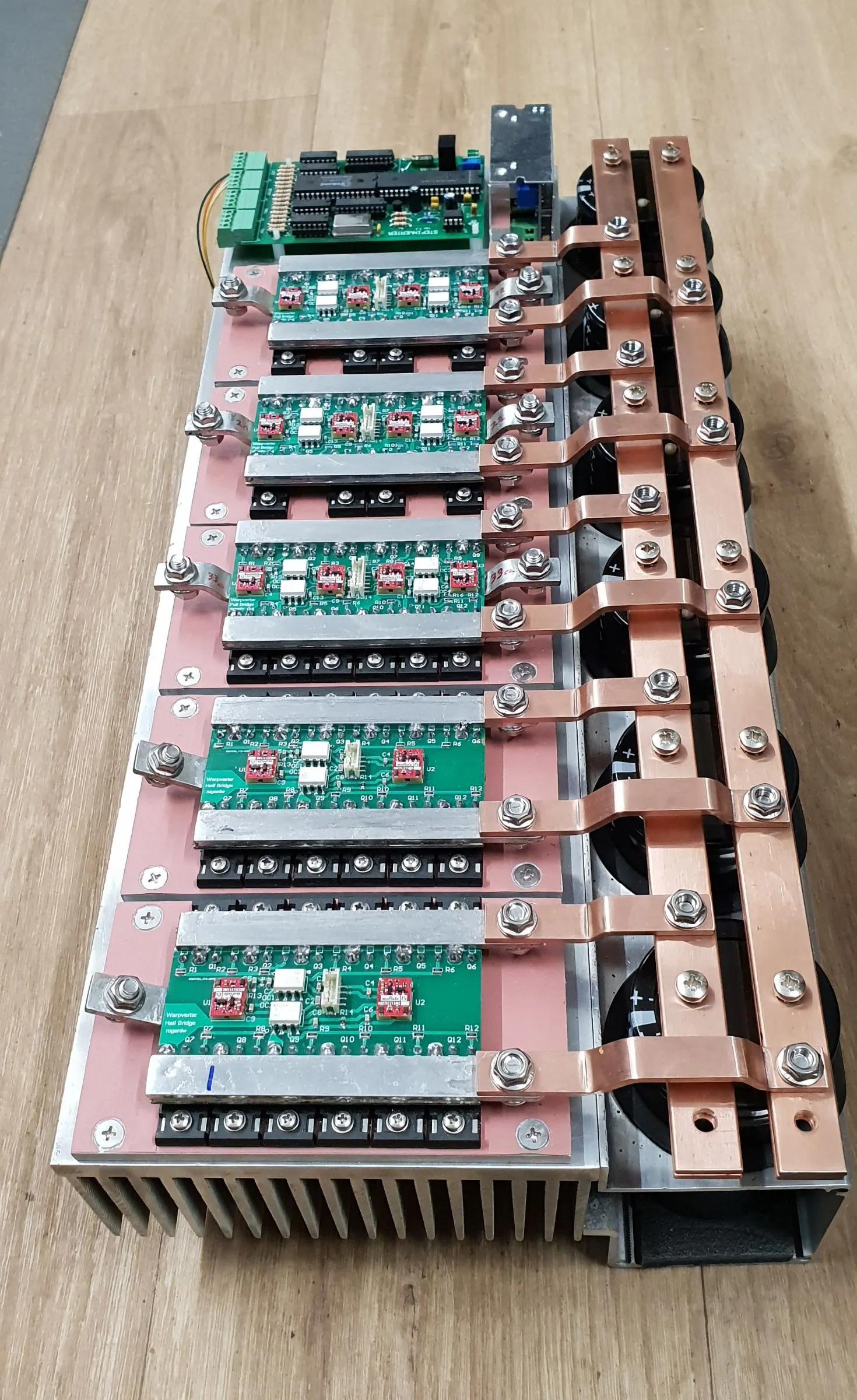
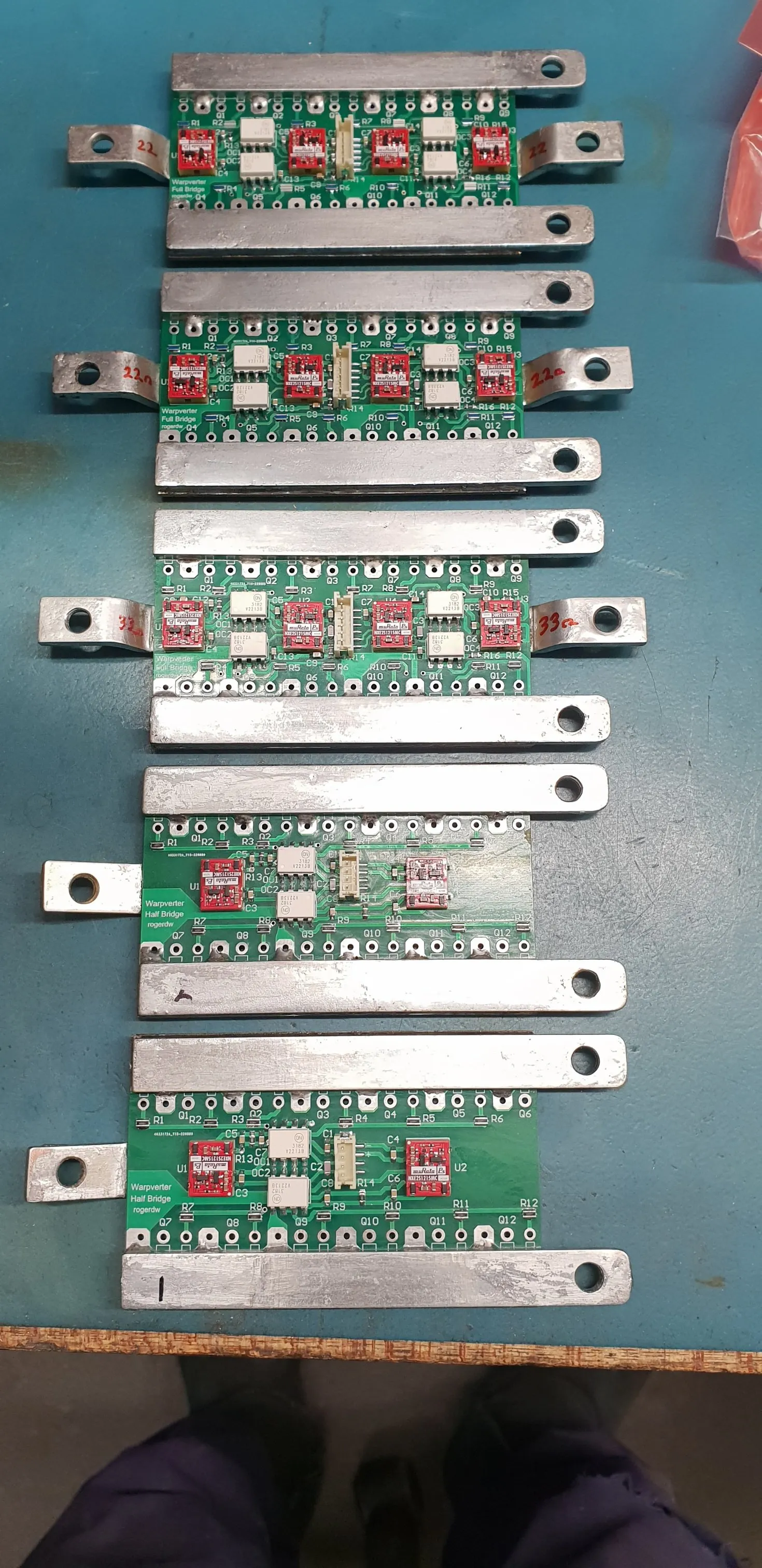
Regardless, I dove in and started designing the layout I envisaged using … learning to use a pcb layout program and creating my full-bridge and half-bridge modules … with the idea that I would build spares so that if I ever had any blow-ups, it could be more easily repaired.
I also wanted to build a number of the MPPTs that ‘Poida’ was developing on thebackshed … and ‘wiseguy’ was kind enough to give me the files for his version of the board for me to develop further, by adding the two Arduino Nanos onto the main board.
Having been an electronics tech all my working life … and particularly disliking working on badly laid out equipment … it was important that my unit be easy to access and work on.
I also started chasing toroidal transformers out of scrapped Aerosharp Inverters from solar repairers and installers.
Unfortunately I have a bad habit of procrastinating … and in the process of planning the inverter I was side tracked by a couple of other projects … so this all got dragged out over several years.
I also spent many hours looking for information on winding toroids and while I found plenty of videos on machine winding … I couldn’t see that being easily adapted to manual winding.
I eventually reached a point where I realised I could waste the rest of my life “looking into” building a Warpverter … or get my finger out and just build one.
Once I had made that decision and decided on the size I was aiming for … Warpspeed was extremely helpful, advising on toroid sizes, turns ratios and wire gauges etc etc and providing heaps of support.
It had been recommended I start with the smallest toroid … and that turned out to be great advice … and by the time I got to the big one … I had a lot better idea and confidence and it turned out very well.
It had always amazed me that the OzInverter guys would reuse the wire from the toroids they unwound … and I never read of any issues in doing that … so I did the same for the smaller three toroids.
With the large one, I bought new copper wire, not wanting to take any chances.
Looking back at the winding process, it turned out to be relatively simple … just requiring patience and perseverance. Once you know what size wire you need and how many turns … you just have to go through the motions.
I think if I could have found some comprehensive instructions early on, I’m sure I would have been a lot more confident and started far sooner.
So for that reason, I’ll make a real effort to explain and show how it’s done over on the Transformer Winding page … to give others wanting to learn, a head start.
That’s also part of the reason for setting up this website … so anyone interested in building a Warpverter can find all the instructions and clues in the one spot and not have to search all over the web.
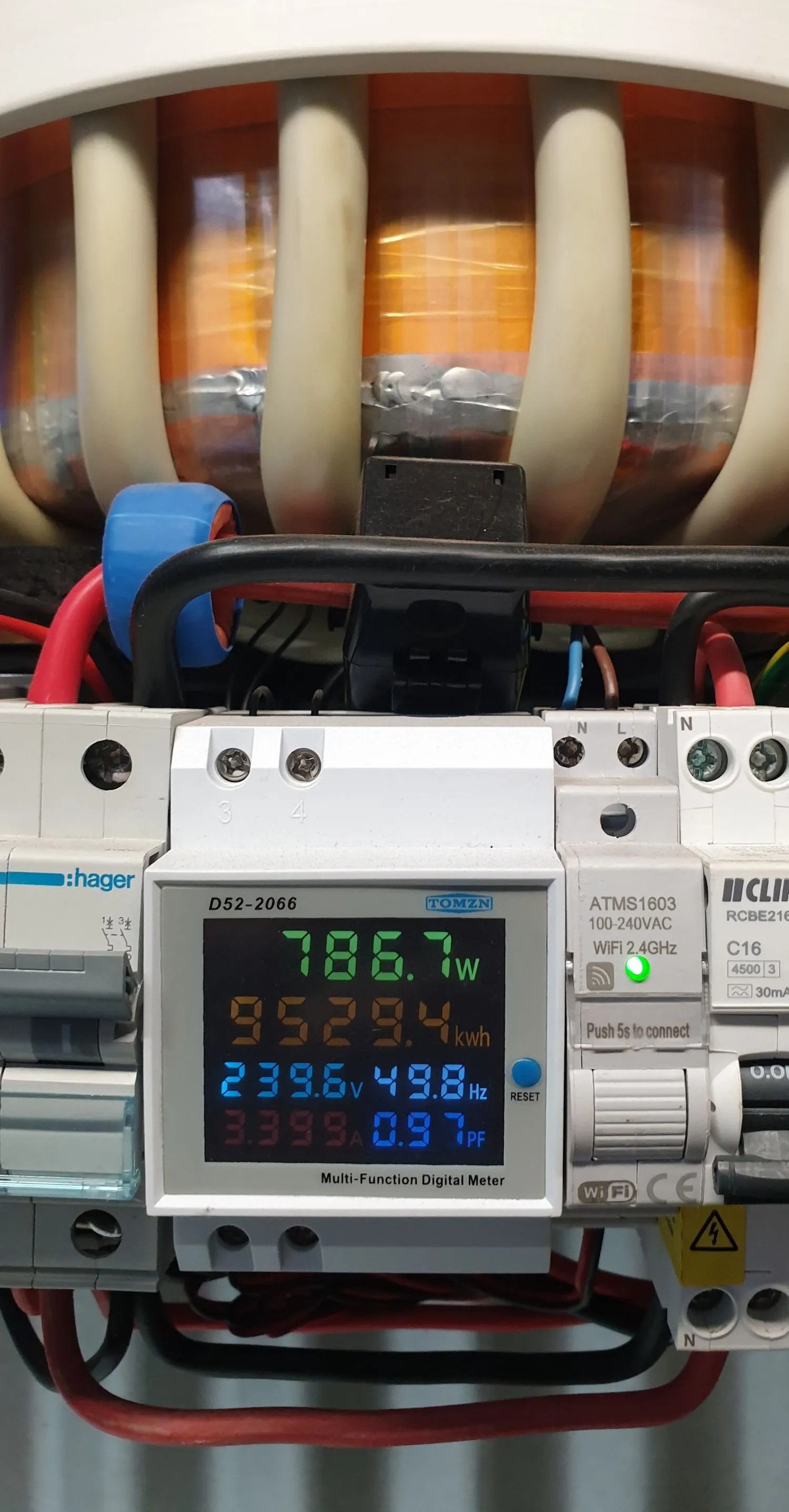
While the Warpverter has only been in action for nine months, it has clocked up 9,500kWh ... and I have had plenty of time to think how I would tackle it if I were to build another ...
... not that I plan to ... just working through how I would advise anyone else considering building one.
While the module idea with the multiple mosfets has worked fine ... I'm inclined to think I would use Tony's system and use IGBT modules if there were a next time ... at least for the larger two inverters.
I had come close to using them myself ... but the expense of each IGBT device scared me off ... plus the voltage drop across them when switched on is still quite high ... and with a battery voltage of just 48V ... I was afraid the efficiency would suffer.
Of course, until someone tries it we won't know.
Another thought is that while we all worry about idling power and trying to keep it at a minimum ... with a 10-20kW inverter ... even if the idling power were to double or triple ... it's not really the end of the world.
I've come to the conclusion that while mine does work beautifully, it would certainly be easier to follow Tony's method of construction for the quickest and easiest build.
Blowups!
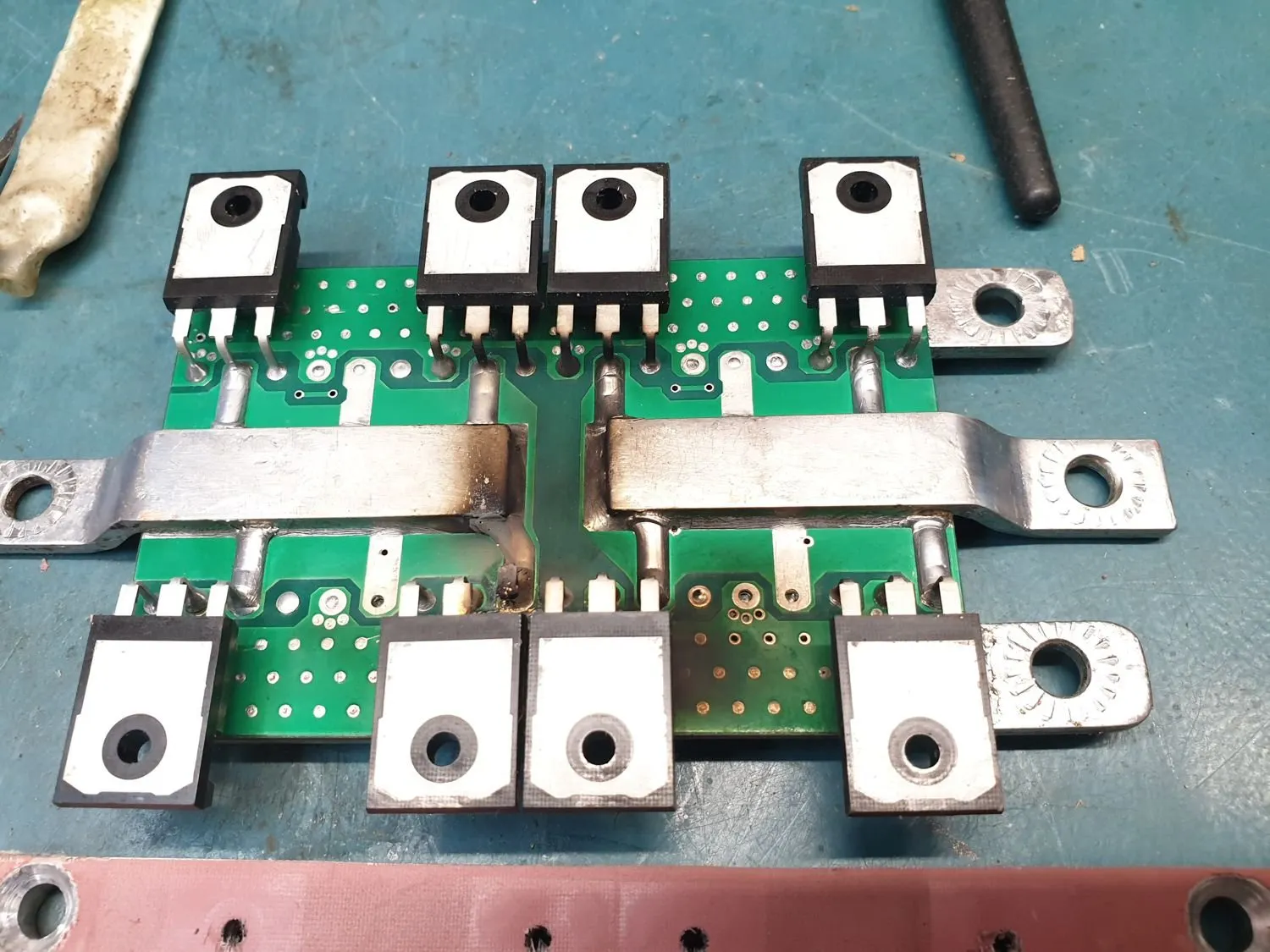
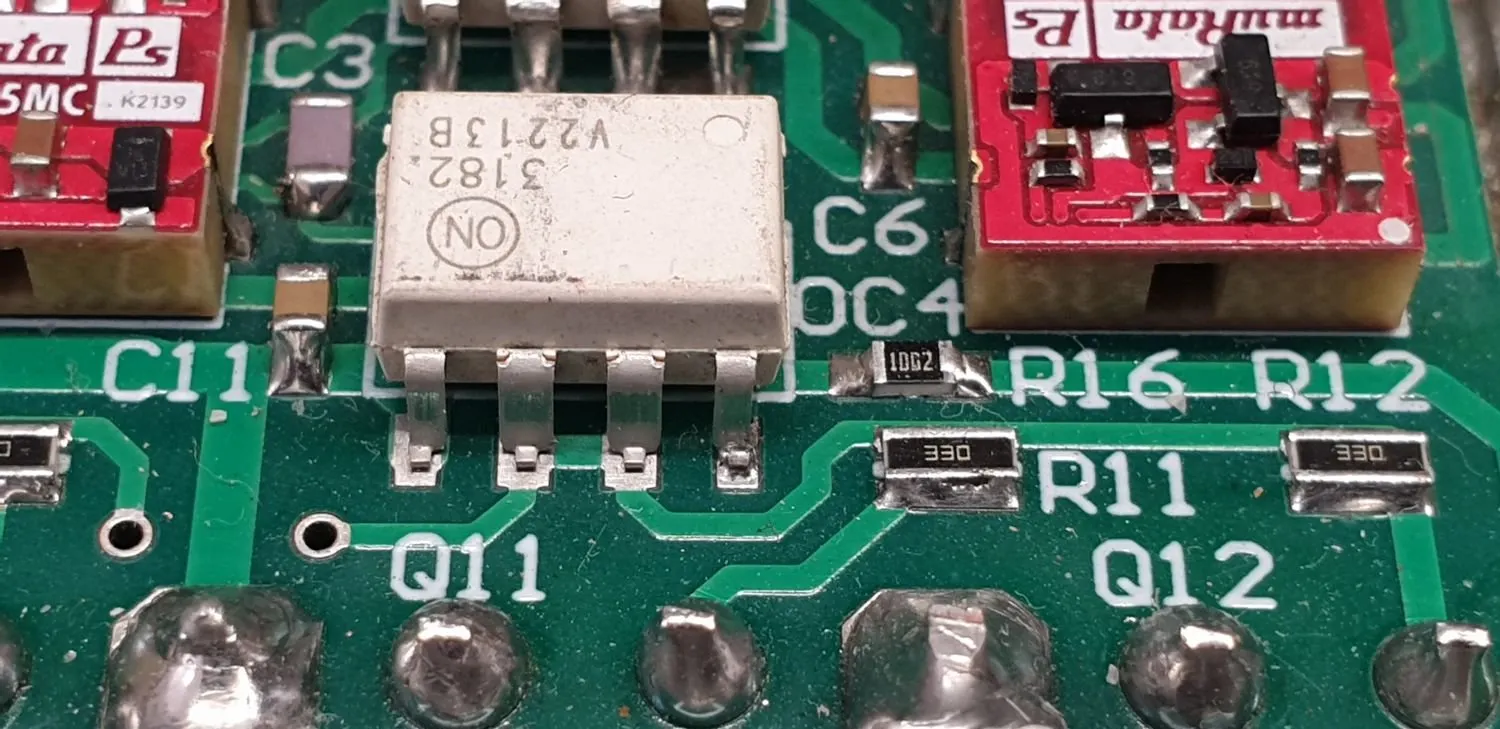
Of course there were some issues when I first fired up my new build. It was only a few minutes at very low power before a few mosfets went bang. On close inspection I discovered I had not soldered all connections on one of the smd opto-couplers and isolated supplies on one module. Whoops!
Then an hour or two later, another heap went bang and I was starting to question building my own inverter. Once I calmed down and started thinking a little clearer, I realised I hadn’t paid any attention to the “dead time” I had set on the boards … the time between when one set of mosfets in the bridge turn off … and the other set turn on.
Not surprisingly, if the second set turn on before the first are fully off … there is effectively a dead short across the battery … and destruction is assured.
I had used the same value dead time caps that Tony had used for his build … but as he was using IGBT modules, his settings were quite different to what was needed on mine.
All that was needed to fix this, was to change a total of eight dead time caps from 1nF to 10nF … which increased the dead time from 230nS to 2.3uS. Tony has suggested it could be increased to tens of microseconds if there were any more dramas.
Some weeks later, after the unit was installed and had been running our property, another batch of mosfets blew up. I promptly replaced them and not finding anything else wrong … switched it back on.
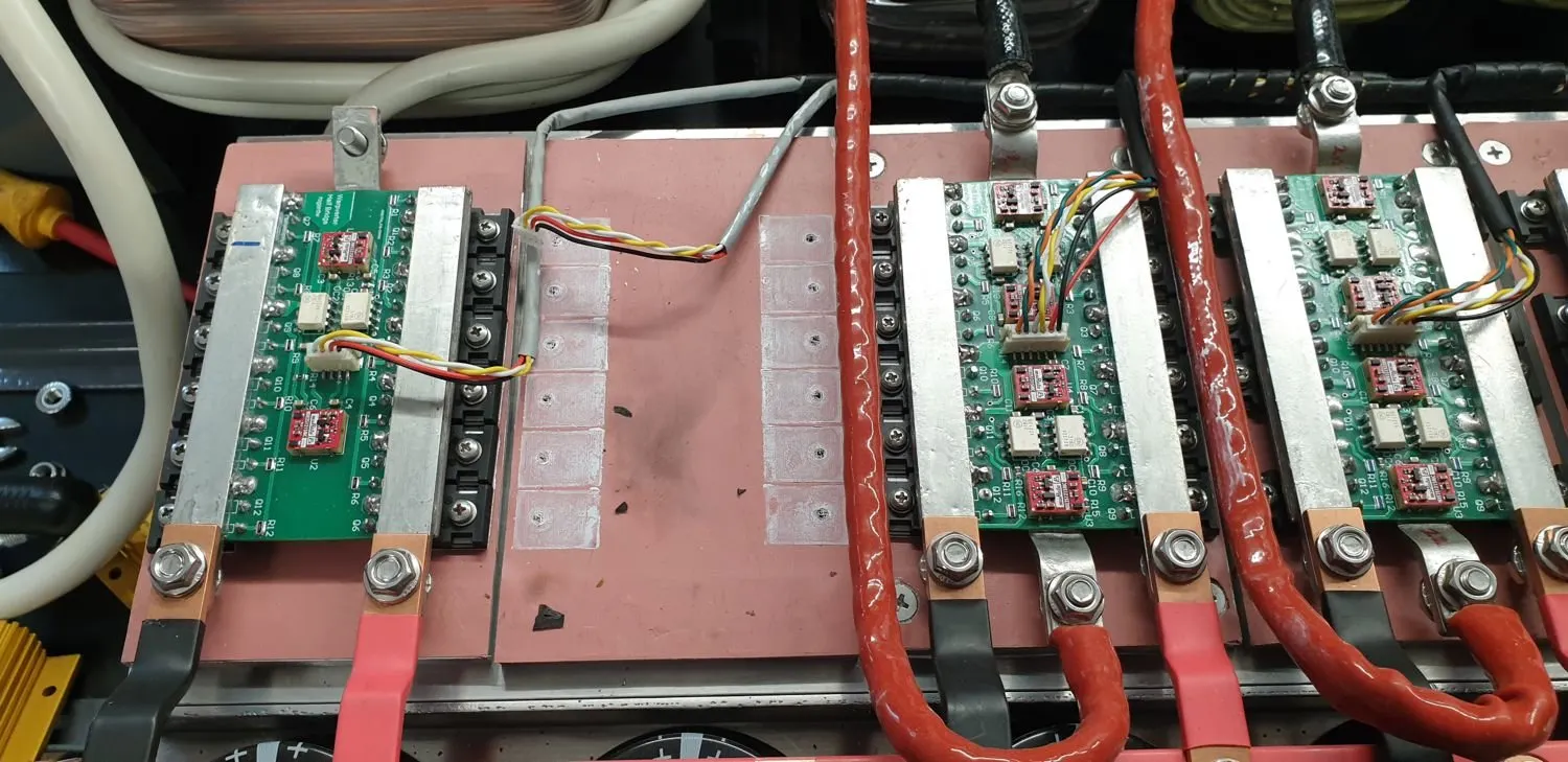
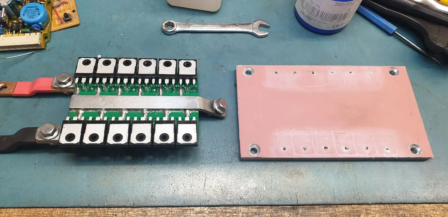
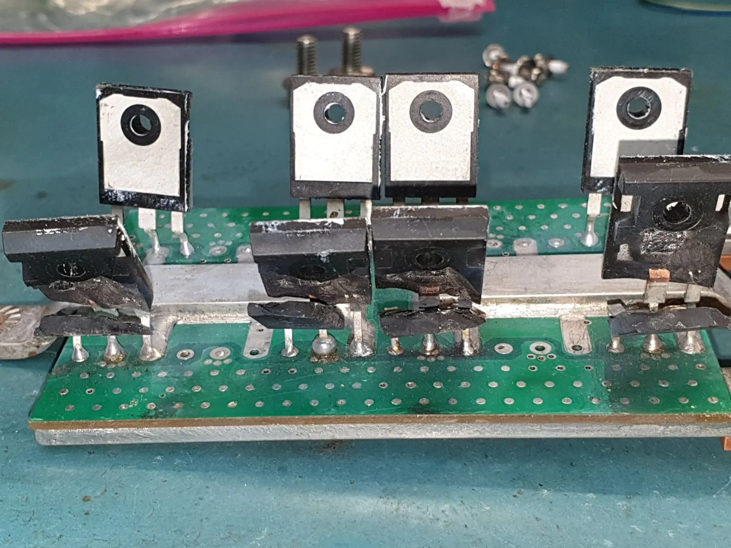
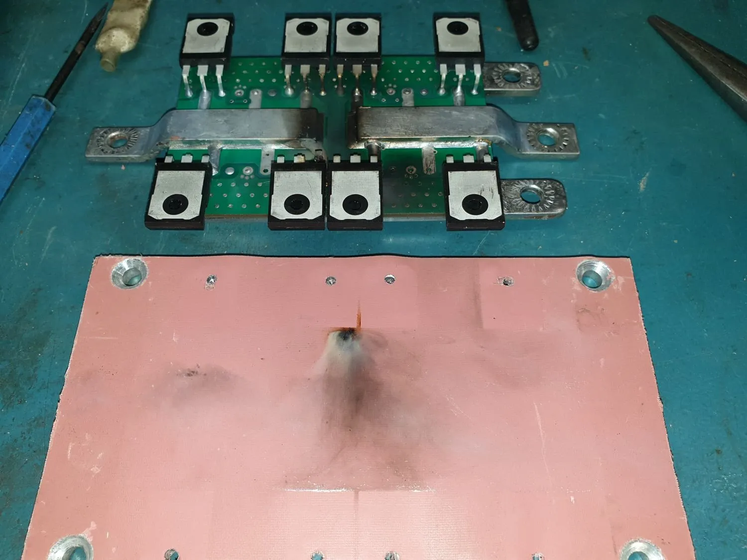
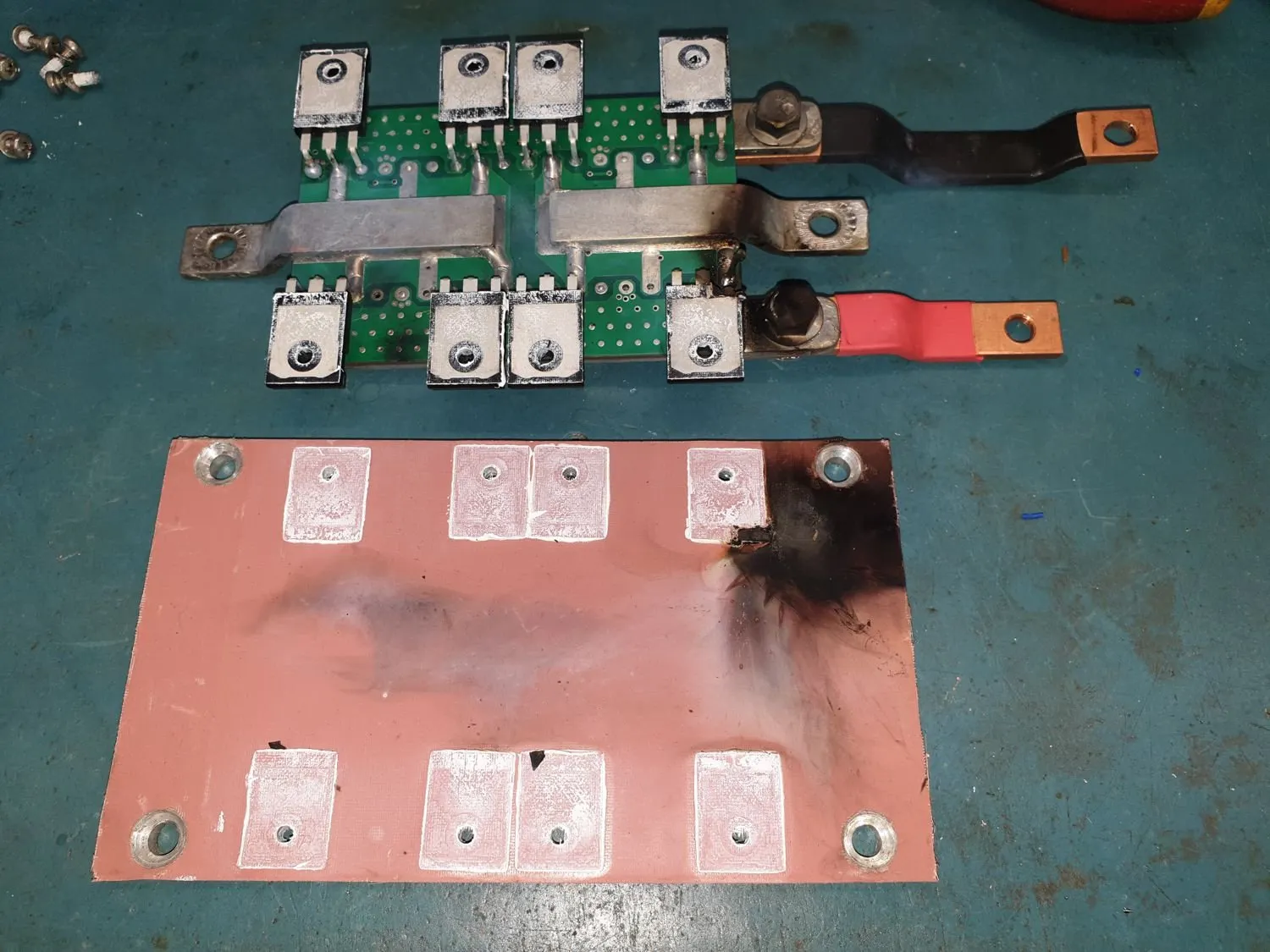
It only ran for half an hour before failing again. On inspection, I wondered if I had damaged (or the exploding mosfets had damaged) the insulating material between the mosfets and metal backing plate … so I fitted new insulation material along with another set of mosfets
That seemed to solve the problem and it has, touch wood, been running for the last 8 months trouble free.
I did search for actual mica washers the size I need … instead of using the pink rubbery type that I started with … but can not find any big enough without using a number per module.
The original material I bought came from a mainline electronics supplier … but I was suspect about it from the start because it was folded, rather than rolled when I received it … and the folds had creased and cracked the surface. I had avoided the creases when I cut it out … but I suspect it had all started to disintegrate.
I bought a new roll from aliexpress, on recommendation of other builders … and that material, despite being a quarter the price, seemed a lot thicker and more supple. If any of the other modules need work at any stage, I will certainly replace their insulation too.
Scroll sideways through these photos to see some of the carnage.
As far as exploring power limits, I was extremely timid to start with ... especially after a few FET exposions ... but as I gained confidence I slowly increased the loads.
I had run it on a trolley for a couple weeks ... hooked up to the forklift battery I had bought ... 48V 980aH.
It was summertime and there was plenty of charge current available via the 6.6kW of panels I'd fitted and the pair of MPPTs I had built ...... so I ran the pool filter pump and pool heater pump during the day every day for those weeks.
It seemed happy enough and I would add extra loads ... a heater (in summer!!!) plus boiling a kettle and using the boiling water on the weeds around the shed and the fencelines (excellent weed killer).
I ran loads at length up to just over 5kW and all seemed fine ... so it was time to organise an electrician to hook it all up.
That went smoothly and he fitted an ATS (Auto Transfer Switch) in the main meter box so that it would automatically switch back to the grid if anything failed or I turned it off.
The ATS works quickly enough that it doesn't bother any computers or digital clocks ... though I do notice some old type fluros in the shed give a flicker at switch over.
Daily Useage
Once the inverter was connected to the house I stopped thinking about what loads were being thrown at it and figured it was either going to sink or swim ... and I slowly became more confident as I saw the normal daily use hit some fairly high levels.
We have an all electric home with two ovens, dishwasher, drier, rainwater pressure pump, pool etc … with a gas hot water system ...
... and because we were always wasting so much water waiting for hot water to come through ... we had fitted a couple of electric under sink water heaters as well. Power hungry devices!!
I marvelled to see the ovens on, the cooktop going, along with the microwave at times … and when the hot tap is turned on, the pressure pump and the under sink water heater also firing up. Massive loads. :)
And I was amazed to see the Warpverter take it all in its stride.
I don’t know how some people manage off grid … but my decision to go big and not try and control our power useage was a good choice. That’s not a fight I would ever have won here.
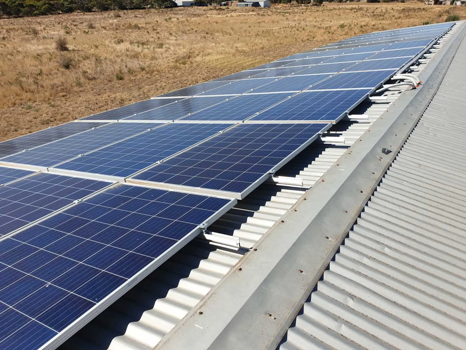
After only a few weeks of it being installed, I realised I could run more stuff if I had more panels … so I fitted a further 6kW of 250W panels (that I had bought some time earlier) to the shed roof, for a total of 12.6kW.
I hooked up the extra two MPPTs I had built and it all went smoothly.
It wasn’t unusual to see 9-11kW of power being used at times … though of course it throttles right back the rest of the time.
AC-Coupling
With Autumn starting to kick in … and me not feeling all that enthusiastic about chasing our winter wood supply … I figured if I had MORE panels, I could run even more stuff … like electric heating … and save a lot of effort with wood.
I very quickly found another system on marketplace … 6.6kW of 440W panels, a 5kW Growatt GTI … and all the roof mount railing … for $1,000 AUD. Absolute bargain … except that I had to uninstall it first!!!
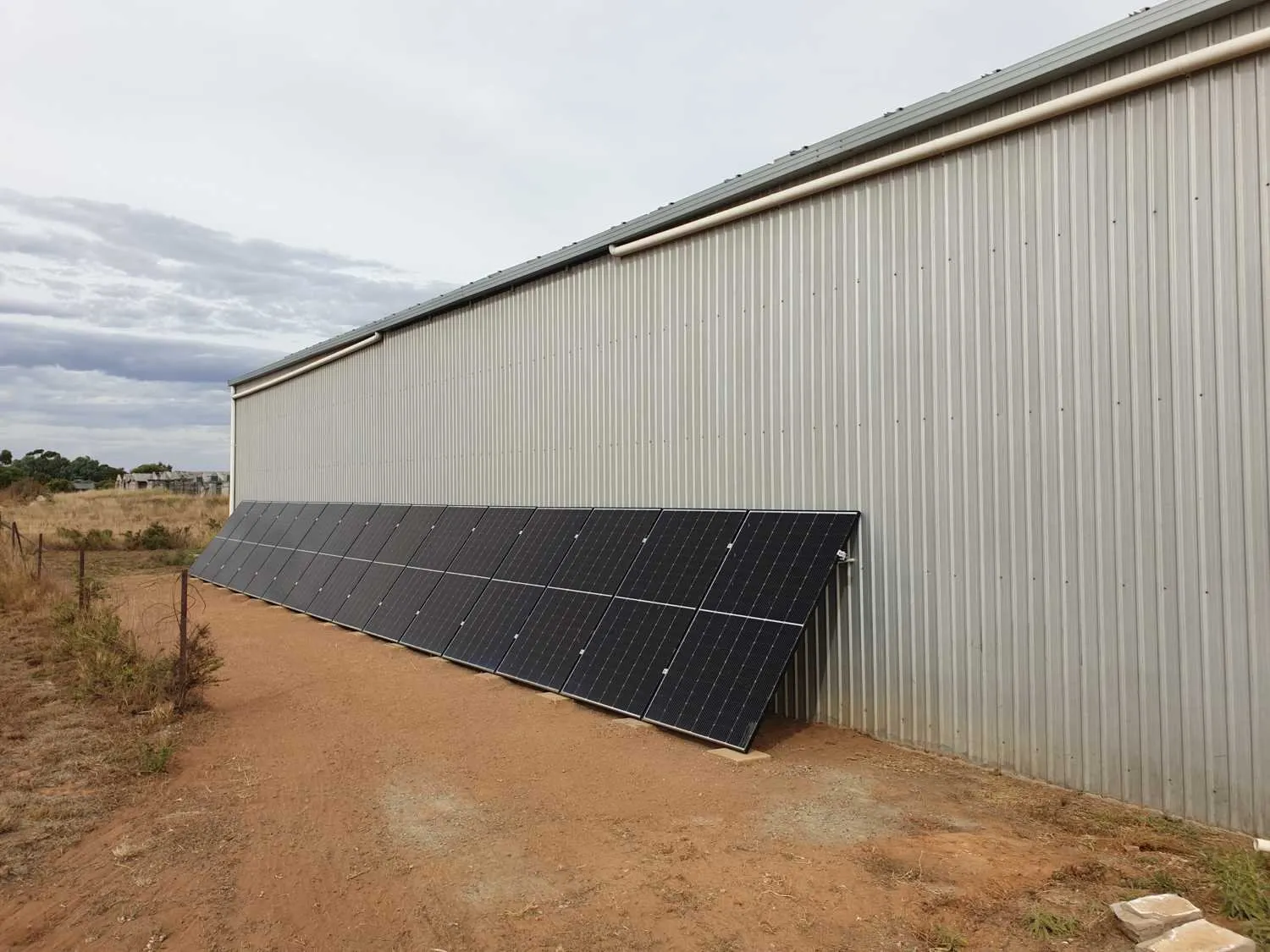
Fortunately my brother in law was visiting, so he and my wife came along to help with the work. When I got home, I leaned the panels up against the north facing shed wall (southern hemisphere) in two strings … fitted the GTI alongside the Warpverter and connected it all up.
It took a minute to sync … and then very slowly started ramping up … with the Warpverter ramping down by a similar amount as the Growatt started sharing the load.
And again, I was amazed to see the Warpverter take it all in its stride.
It took me a while to understand what was happening once it was running. Normally our morning house loads might be around 1kW ... but I would look at the power meter and see 2 or 3kW ... and the Growatt showing a couple kW as well ... which didn't make sense.
It was only when I was looking at the clamp meter and finally realised that all those amps were going in to the battery and not out of. :)
The Growatt was feeding back through the Warpverter and into the battery.
With AC-coupling, I had understood the worry would be that the battery can be overcharged as there is no control over the back feeding.
We got away with it because as soon as there was excess power available ... I found something to turn on. I work from home, in the adjacent section of shed so it's easy to keep an eye on it ... and simply switch off the Growatt if it looks like generating too much.
Once I realised just how much power we were generating, I started running our underfloor heating circuits (2 x 3,000W) as often and as long as power was available.
And often with still plenty of extra power available, started turning on space heaters as well. I eventually bought a couple of wifi controlled 2,300W heaters that I could switch via my phone and set timers etc. It wasn’t unusual to have 10-12kW of heating running most of the day while the sun was cooperating ... split between the Warpverter and the Growatt.
Of course from later afternoon it was all turned off so the battery would survive the evening's cooking and overnight loads.
As winter kicked in I used the wood heater to see us through … but from normally running the wood heater for five months of the year … this season we ran it for just two months. Massive saving in effort, finding the wood and feeding the fire.
Spare text box.
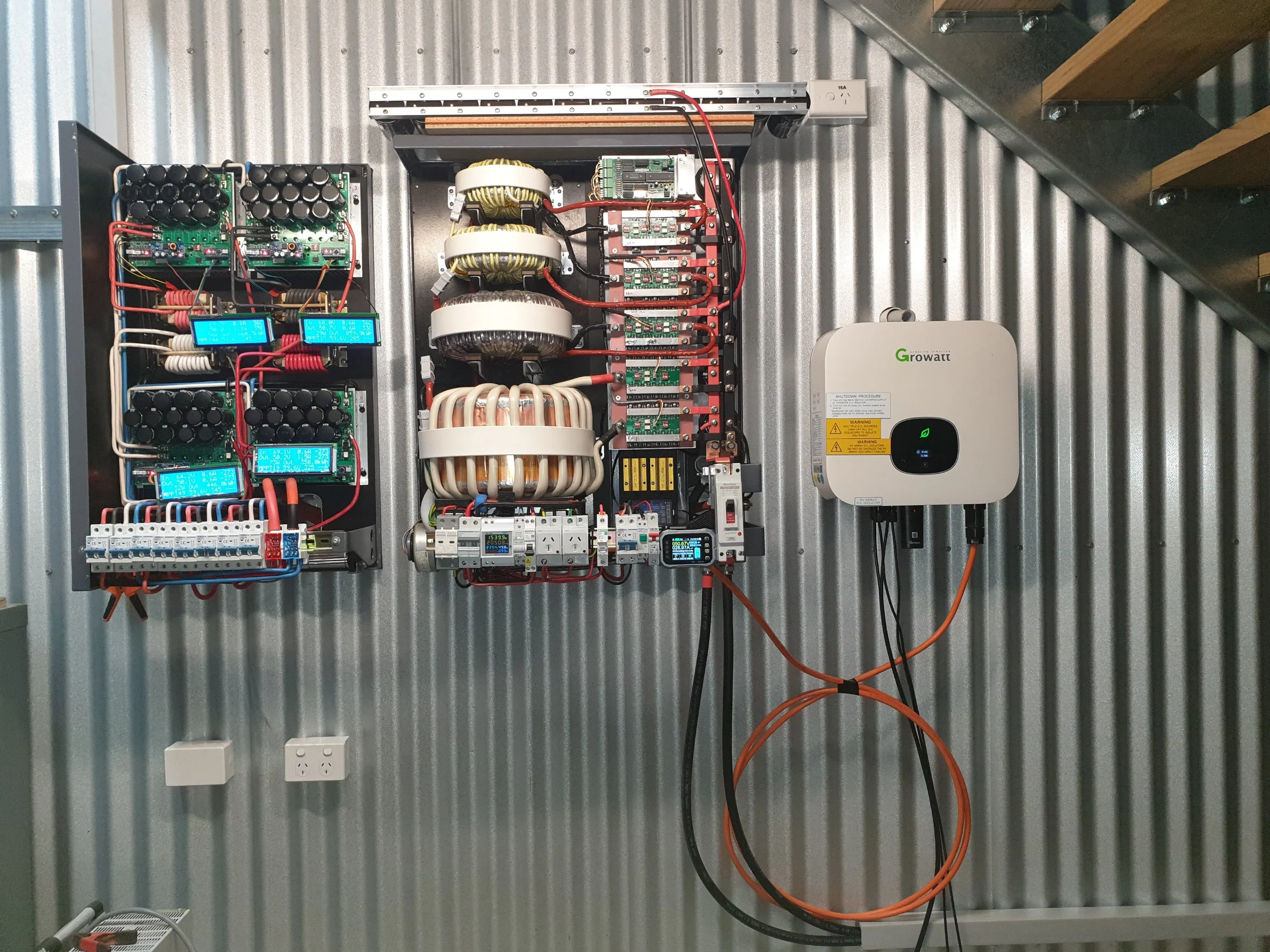
Roger's 15kW Warpverter, MPPTs and 5kW Growatt
Warpverter Layout
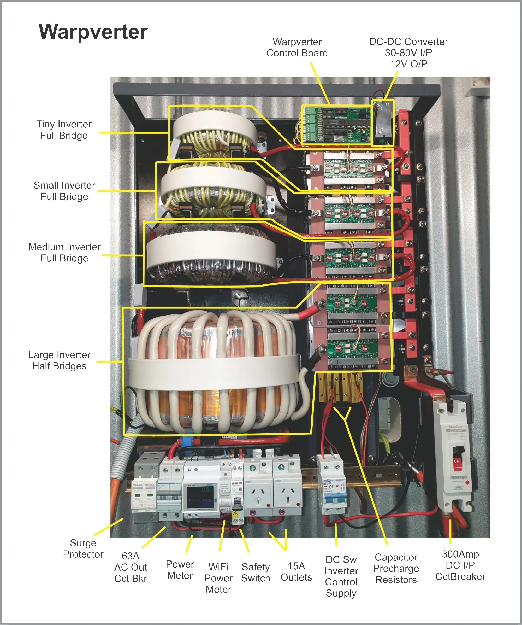
Here you can see the basic layout of the Warpverter
This one uses a 48V supply via a 48V 980aH Forklift battery
(FLA Flooded Lead Acid)
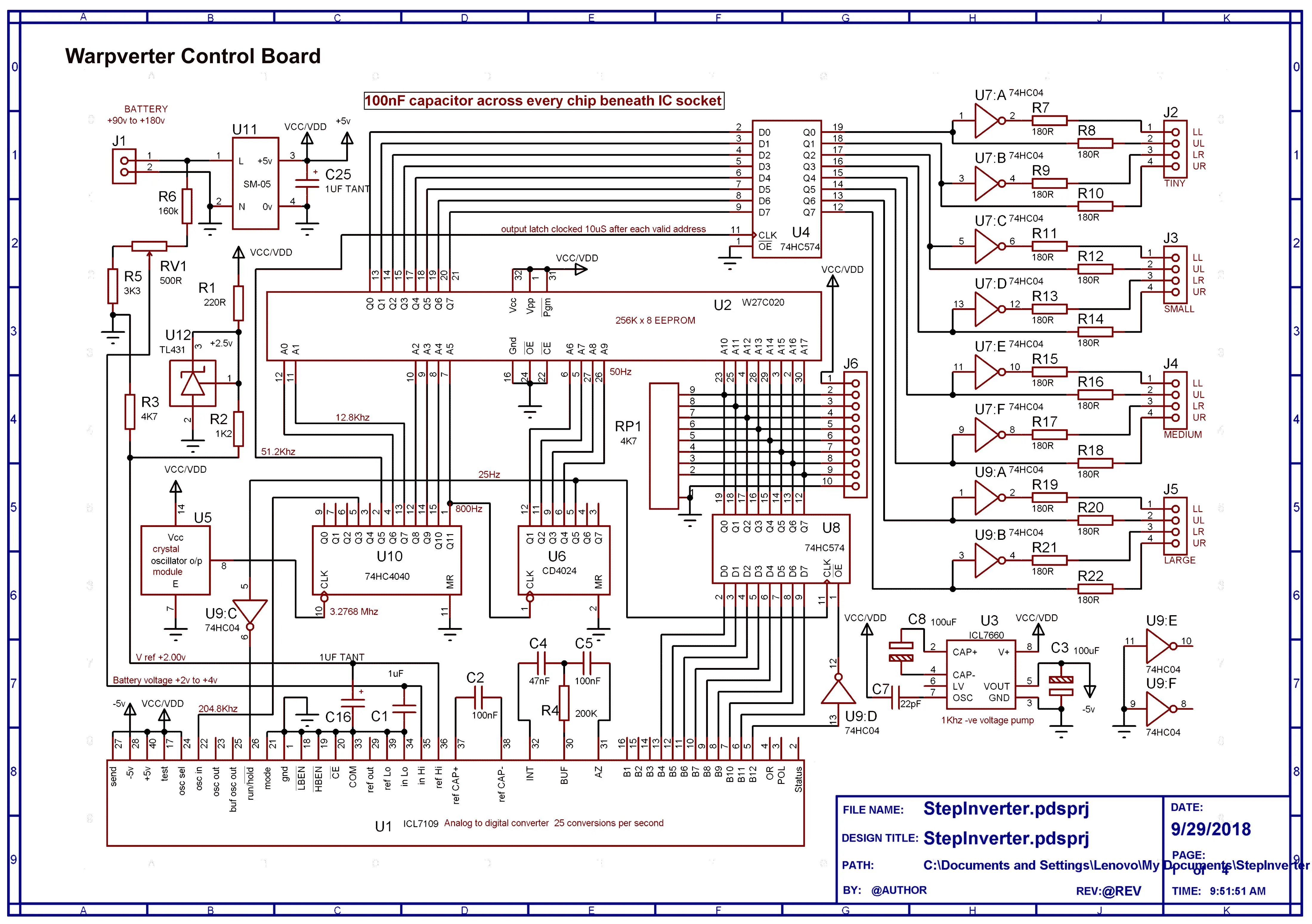
In the top RH corner is a 30-80V input DC-DC Converter to drop the 48V down to 12V for the control electronics
And to the left is the control board which provides the drive signal for the individual inverter bridge modules
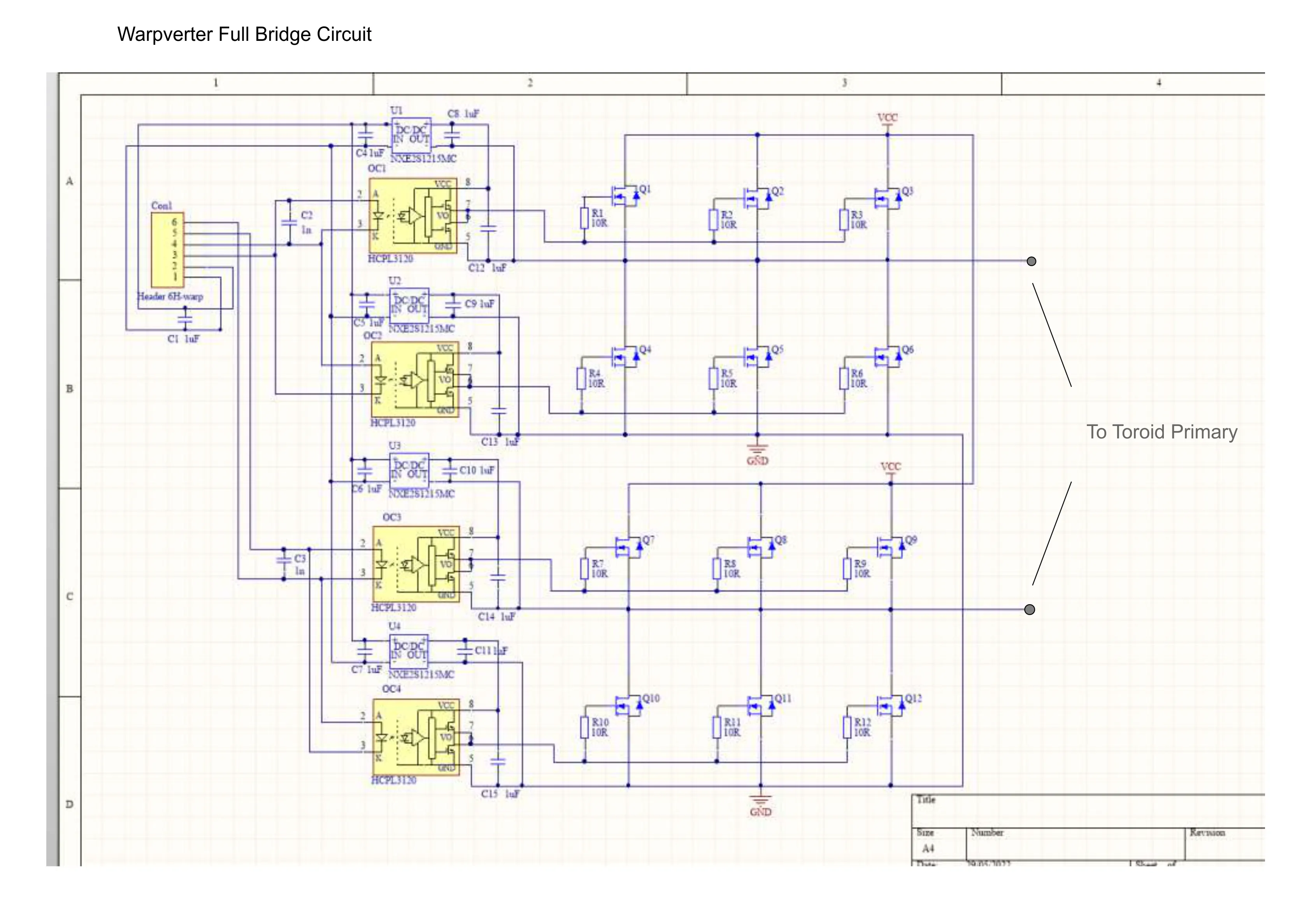
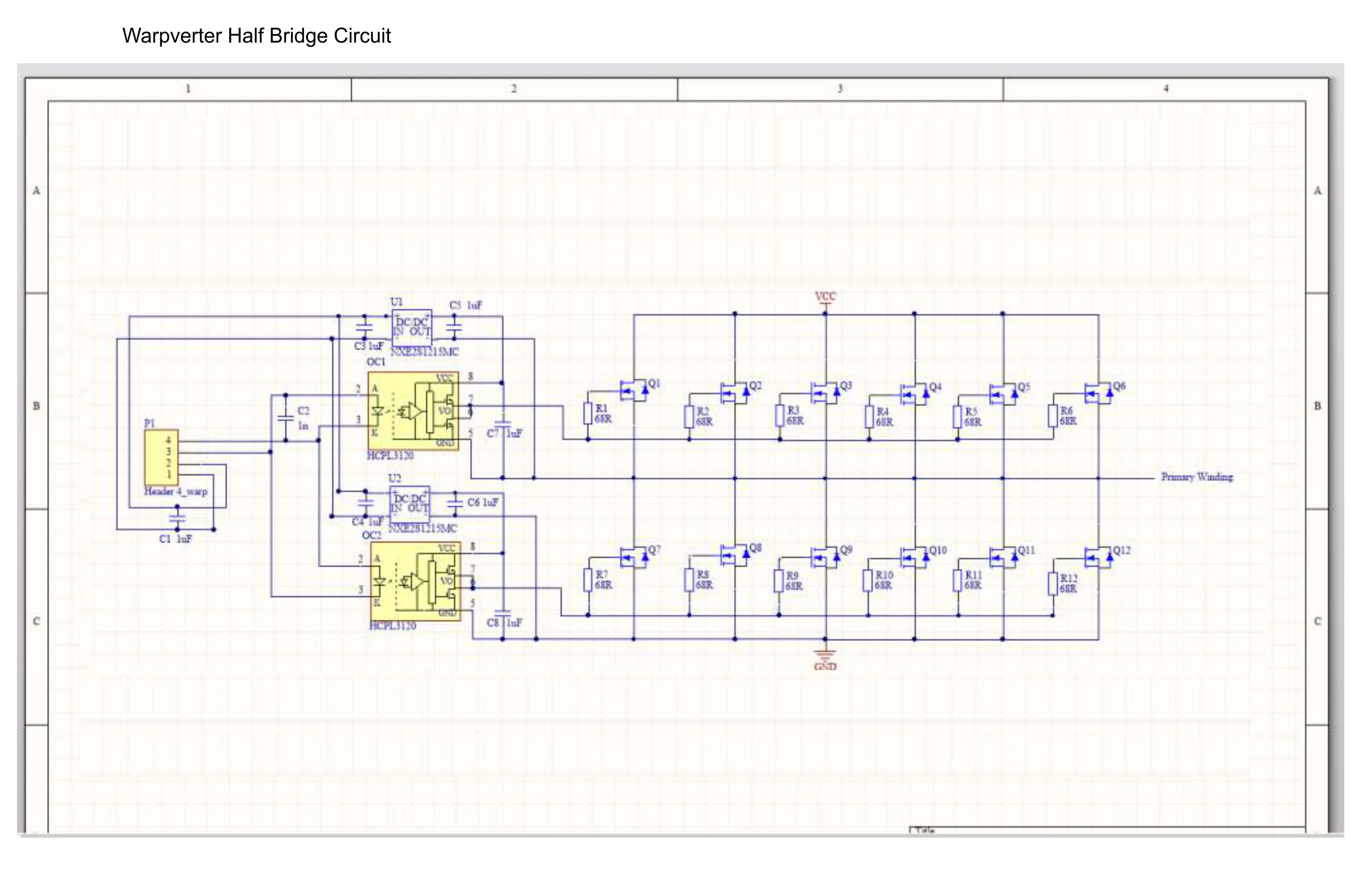
There are three full-bridge modules each driving a toroidal transformer ... and two half-bridge modules driving the largest transformer
Across the bottom is an array of normal AC circuit breakers, a power meter and control devices ... along with a 300A DC input circuit breaker
MPPT Solar Charge Controllers
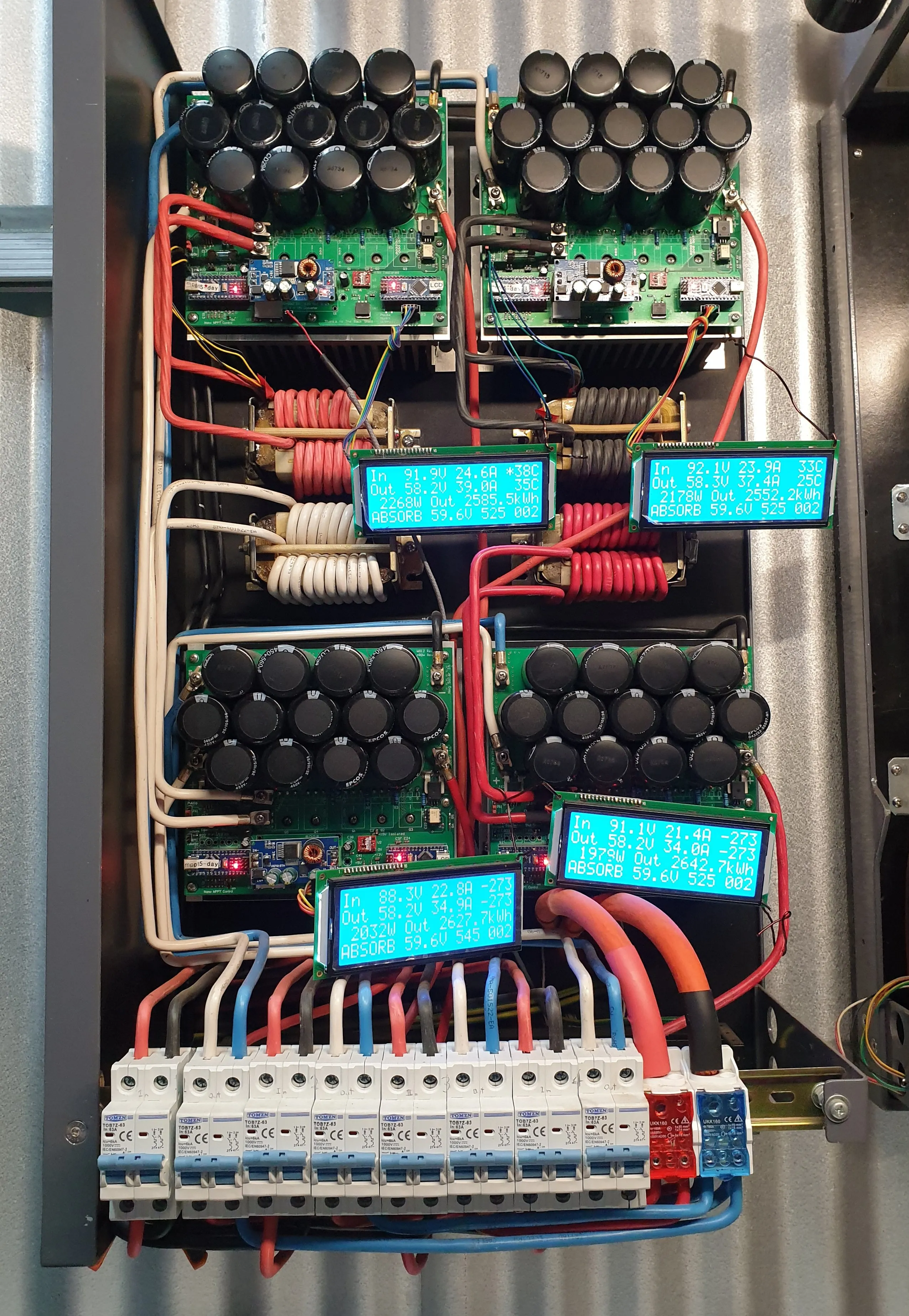
These are the solar charge controllers we use ... 4 x 150V 60A MPPTs ... also a product of thebackshed forum ... see here
If I understand correctly the original concept was by 'nickskethisniks', with 'Poida' developing the software.
A later version of the board layout was designed by 'wiseguy' and he was kind enough to pass on his files for me to develop it further, by adding the two Arduino Nanos to the bottom of the board.
In the last nine months, these combined have generated over 10,000kWh ... and while we needed to do a little overnight charging from the grid occasionally over winter, in the last five months we've needed no additional at all.
Flooded Lead Acid - Forklift Battery
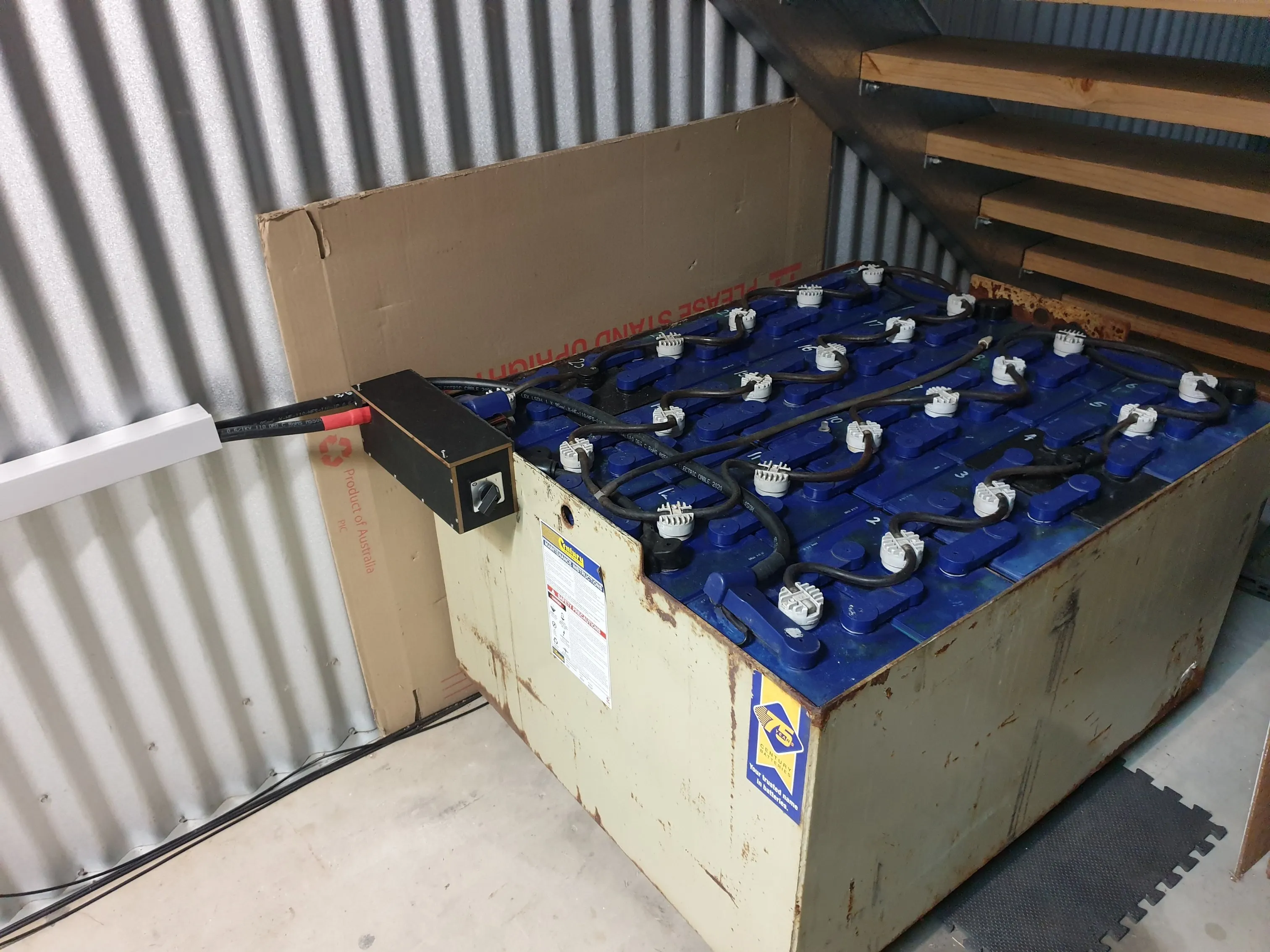
While I initially hoped to find a Nissan Leaf battery or similar to run our system ... there were none to be found when I first started looking around five years ago ... so I decided to design to suit a forklift battery.
This one is 48V 980aH and weighs 1,330kg ... oh and the best part, it only cost $500 ... scrap value.
I have to admit I am very pleased with the choice and love the simplicity. In fact I plan to search for an additional one to run in parallel ... mainly to help out over winter. It's not really needed the rest of the year.
Some Random Photos
To see more detail right click and "Open image in new tab"
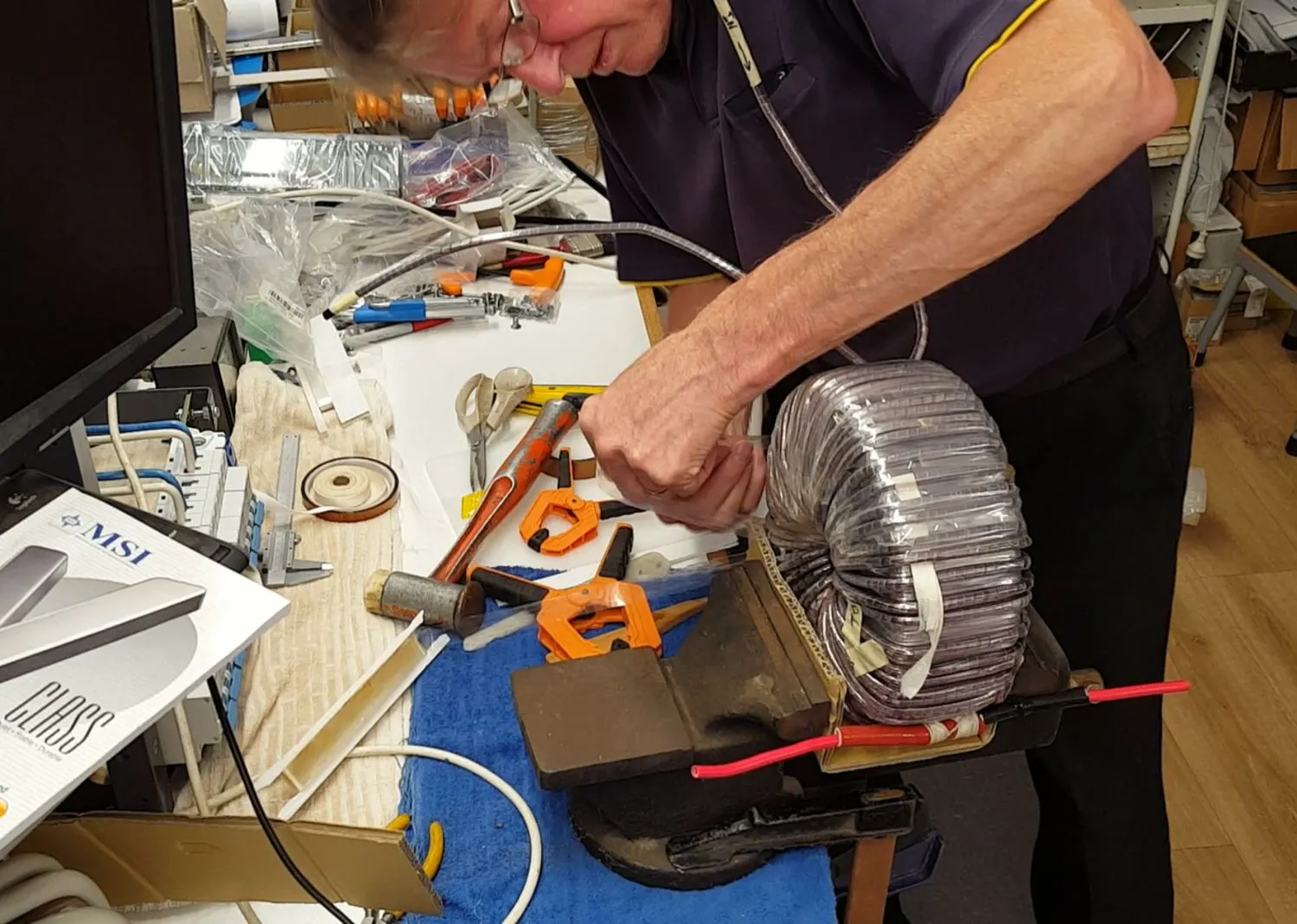
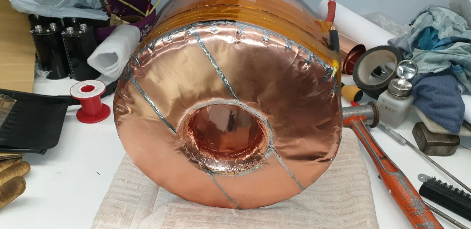
Putting the final layer of mylar tape on the "Medium" toroid. Helps hold all the windings in place
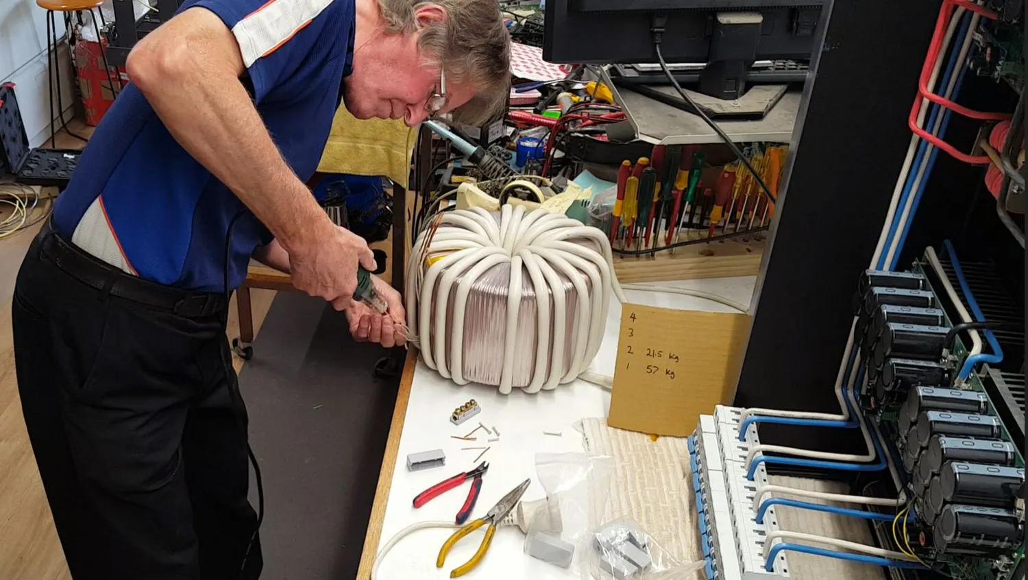
Stripping the enamel off the ends of the individual copper wires using a DF-8 electric wire stripper ... available from Amazon or aliexpress
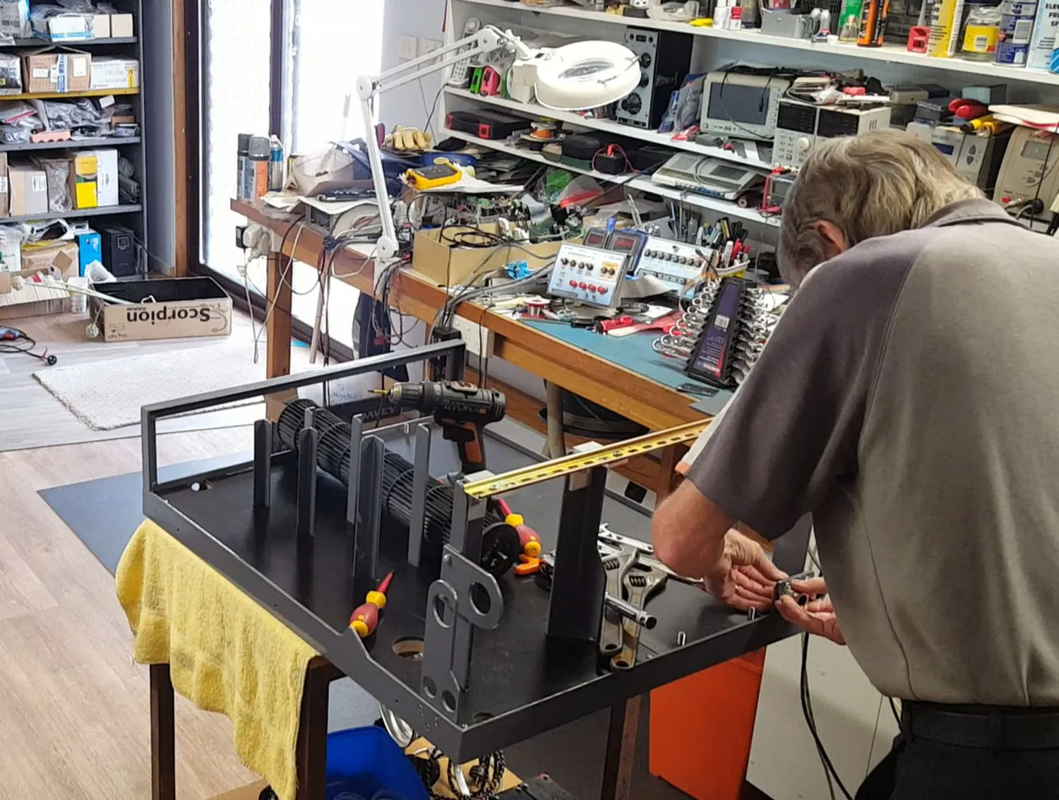
Starting the final assembly
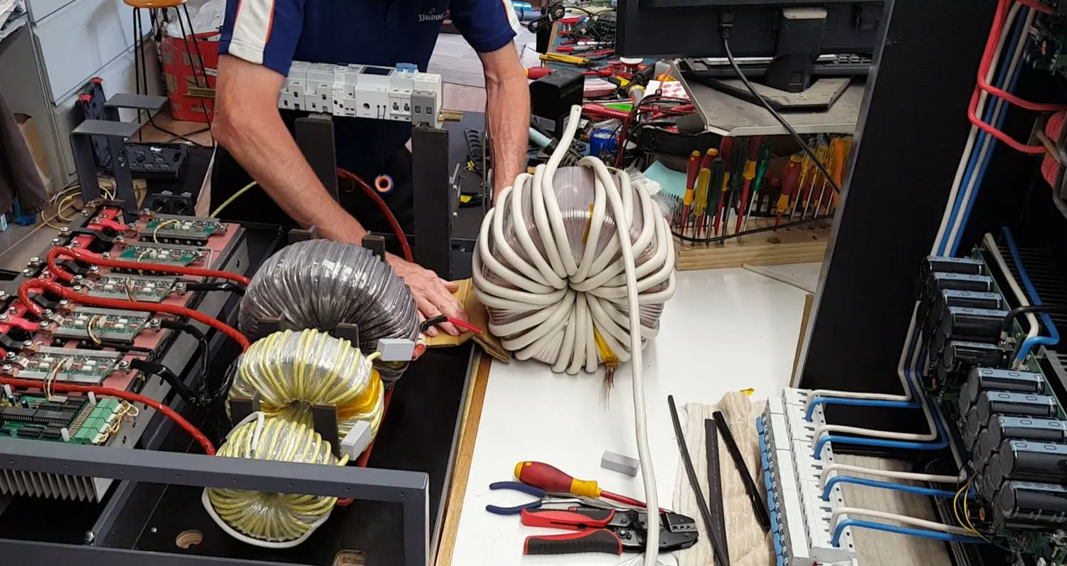
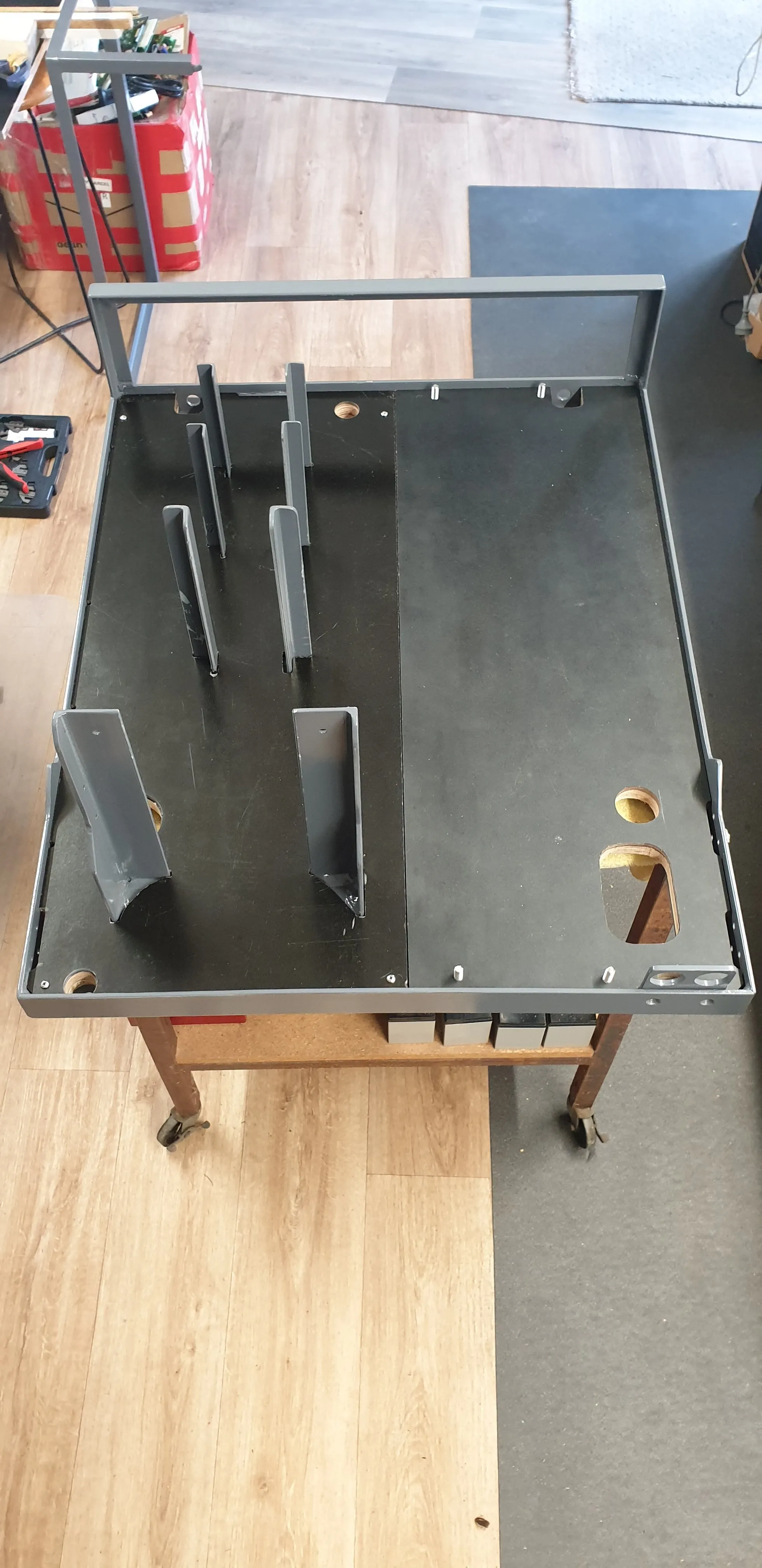
Bit heavy to lift at 57kg, so just rolled into place

Lor
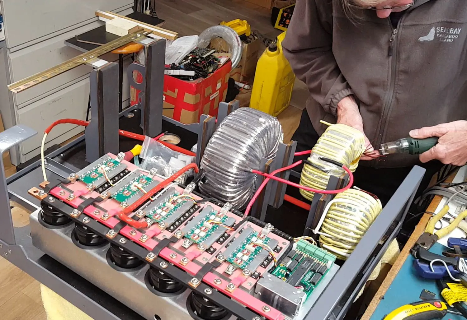
Stripping the wire enamel off the "Small" toroid winding ends
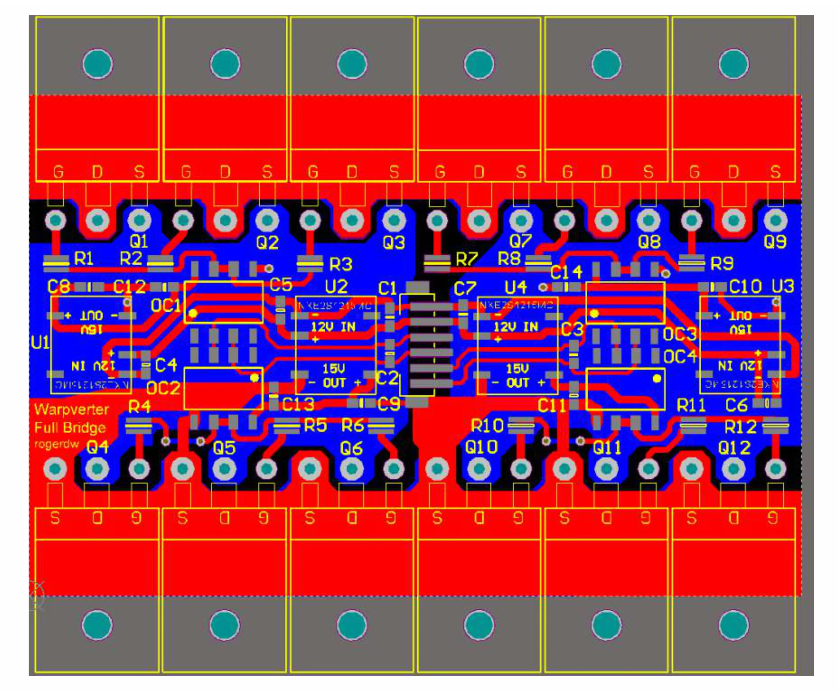
Warpverter Full Bridge board layout
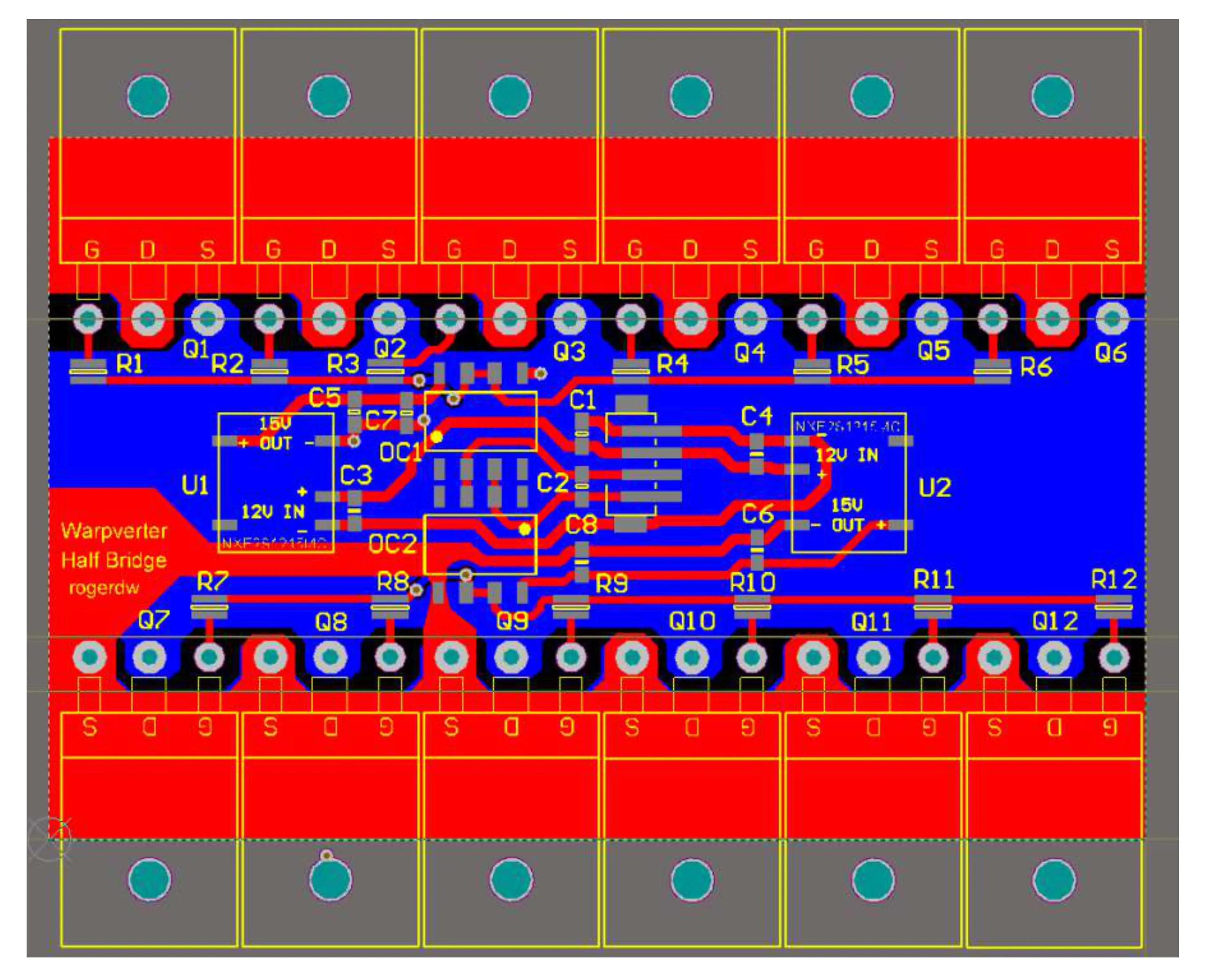
Warpverter Half Bridge board layout
Lorem ipsum dolor sit amet, consectetur adipiscing elit. Quorum altera prosunt, nocent altera.

Contact: Visit this thread on diysolarforum and message Warpspeed or rogerdw

© 2024 Warpverter.com - All Rights Reserved. Terms of Service: Privacy Policy:
