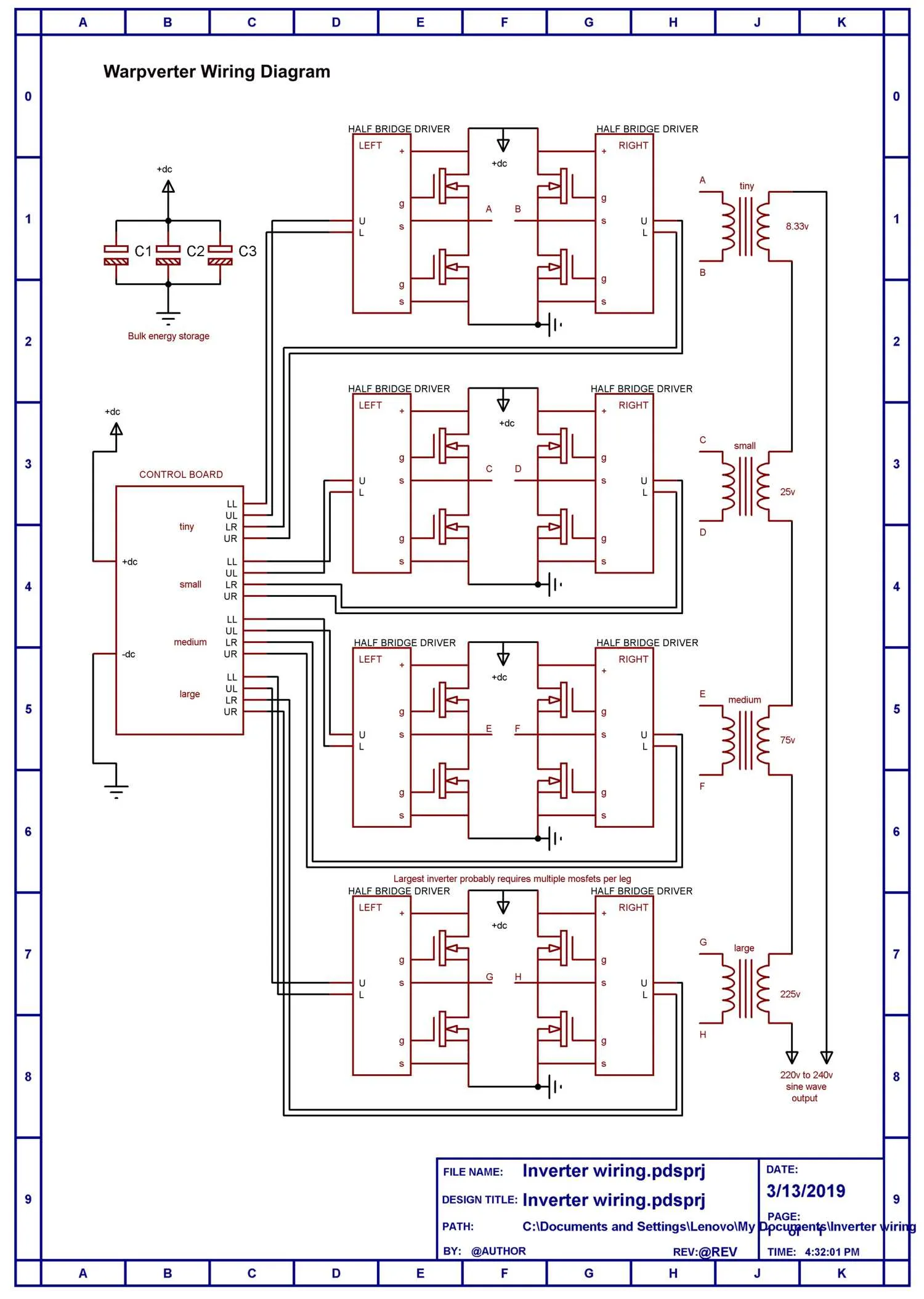
Most inverters use voltage feedback to maintain a constant output voltage with changes of dc input voltage and load.
The main problem with that is its slow to correct.
The correction must be introduced slowly, or it can over correct and become unstable. Sudden large step changes in load (up or down) can cause annoying sags and surges in voltage resulting in light flicker.
The inverter output voltage will eventually settle, and then remain fairly constant.
Feed forward works in an entirely different manner.
The dc input voltage is measured, and the inverter can then very quickly adjust the waveforms driving the output transformers to compensate for any change in dc input voltage. The result is that the reaction time of the inverter to sudden dramatic load change can be made much faster acting.
It can compensate pretty much perfectly for input voltage variation over a very wide 2:1 dc input voltage range.
The down side is that although the transformer primary waveforms are well corrected, the transformer secondary voltages do fall slightly with increasing inverter load.
Voltage droop in my own 5Kw Warpverter is about ten volts (at 240v) from zero load to the full 5Kw rated output. That should be pretty typical, all mainly due to unavoidable voltage drop under load in the transformers.
The grid supply here varies more than ten volts anyway from day to day, and hour by hour, and none of my household appliances seem to mind. So I don't think its necessary to have a precise inverter set output voltage.
What is much more important is to have very fast voltage corrections for sudden step load change, and feed forward correction provides that.
Its especially good at reducing light flicker during the starting of large motors.
Its much easier and faster and more accurate to measure a dc voltage than an ac voltage, which is a constantly changing sine wave at 50/60Hz anyway.
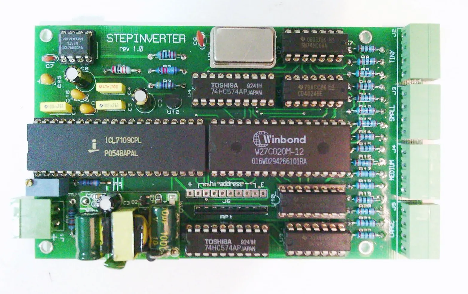
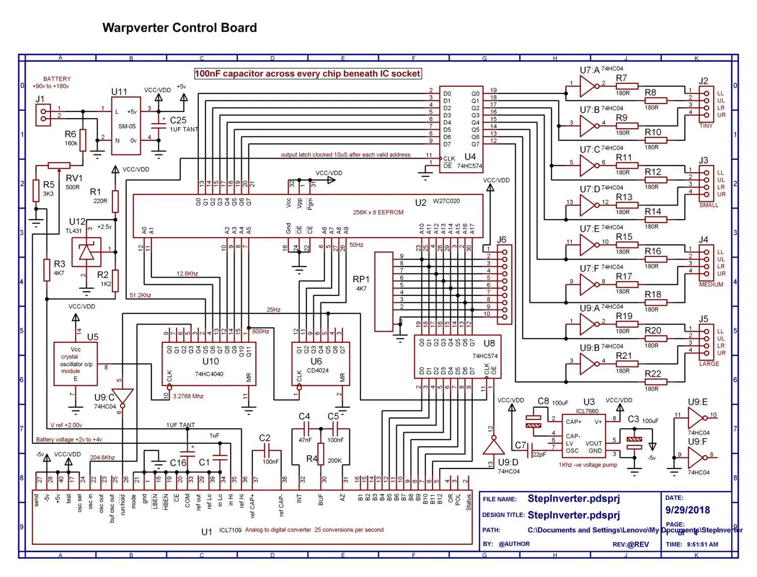
The incoming dc is measured in a dual slope integrating a/d converter (to average out impulse noise) on the dc, and the measured voltage used to address one of 256 different lookup tables in ROM.
These lookup tables cover a 2:1 input voltage range, and allow for a very fine adjustment of inverter output voltage. Large very sudden jumps in voltage correction are possible, and always occur right at a zero crossing, so there are never any waveform discontinuities created from large applied corrections.
This can all be achieved with some simple robust and reliable hardware. The lookup
tables contain direct simple gate drive data to the four power switching bridges, there is no software or data manipulation involved.
