Warpverter
A Serious Electronic Project For The Expert DIYer
Initial Testing
A discussion on testing the various sections of the Warpverter as it's being built ... from the power supply for the control board to the timing of the inverter drivers ... and then to the individual transformers.
Initial testing and what to expect
First thing will be to check that whatever is supplying the +5v dc to the control board will start up and run reliably at the minimum dc input voltage.
Those two dollar wall pack boards from China must be made in the millions, and by countless different Chinese suppliers. They are all the same physical size, and all look the same, but the actual components, especially the small flyback transformer, and start up circuit components can differ.
The tested start up voltage can vary quite a lot typically from around 30v to 45v or sometimes even higher.
If that is a problem, and it might be for a 48v Warpverter, try ordering some more from a different supplier . Your luck is bound to change, and they are certainly cheap enough.
An alternative for the 48v guys might be to use a boost converter to step battery voltage up to 60v or so. That can then power all seventeen of the Chinese wall pack boards without any concerns about minimum start up voltage.
The gate drive signals coming from the control board can be difficult to lock on an oscilloscope. Easiest solution is to externally trigger the oscilloscope off the simpler "large" inverter drive waveform, when looking at any of the other smaller inverter drive waveforms.
"Dead Time" discussion.
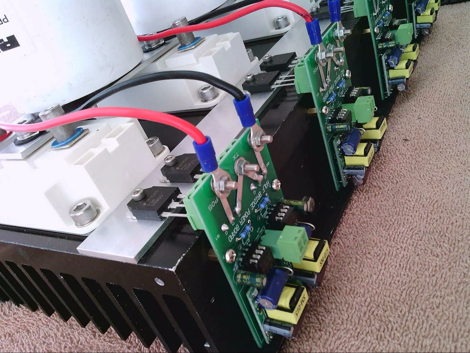
Setting dead time by fitting suitable dead time capacitors to the half bridge driver boards requires some thought. We must ensure that there is sufficient time allowed when switching between the upper and lower IGBTs (or mosfets) so that both are never conducting or partially conducting simultaneously.
There are two factors. The first is the speed of the power devices themselves, particularly the turn off time. And the other is the ability of the opto gate driver chip to charge and discharge the combined gate capacitances of larger or paralleled power devices.
An individual mosfet will be easy to drive fast, both on and off.
The really large several hundred amp rated IGBT power blocks can be quite slow to turn off but still easy to drive.
Multiple parallel mosfets, especially the larger mosfets, can have very high combined gate capacitance, and will be the slowest and most difficult to drive quickly, both on and off.
The opto gate driver can only supply a limited amount of current to charge and discharge all that gate capacitance. A bunch of large parallel mosfets will definitely require extended dead time.
The largest inverter is only switching at 50/60Hz, about 400 times slower than a typical PWM inverter. The dead time can be made extra long, but its still going to be only a tiny fraction of the conduction times at such a very low switching frequency.
We can easily stretch dead time out to many microseconds without any problems at all.
There is absolutely no reason to try and speed things up, switching losses will be very low at such a low repetition frequency anyway.
The test for sufficient dead time is to run each inverter separately without the transformer primary connected, and run an individual inverter switching bridge from a current limited bench power supply.
Try changing the dead time. Power supply current will begin to rise very steeply below some minimum dead time threshold in each inverter.
Select dead time capacitors that are perhaps two or three times that minimum, and you will be good to go.
As a guide, no dead time capacitor fitted, expect to see about 50nS dead time.
1nF dead time capacitor 230nS dead time.
10nF dead time capacitor 2.3uS dead time.
Multiple large parallel connected mosfets might require more than 10nF to be safe.
Transformer behavior during initial testing
Transformers are funny inductive things, and they absolutely hate delivering square wave current.
A working Warpverter reflects a very low distortion ac sine wave current from the secondaries back into all the primaries.
It will run sweetly when its all all connected up, with four inverters finally running, and all the inverter waveforms working together in perfect harmony.
The magnetic flux in the transformers will be a nice swinging sine wave which results in low core losses.
However, during early initial testing, with less than the full compliment of inverters running, be prepared to see some rather ugly secondary waveforms !
So don't be too shocked or disappointed, that is all perfectly normal and to be expected.
Just running the largest inverter and transformer, expect to see 50% voltage overshoot in the secondary, and possibly some ringing, its definitely a very unhappy transformer when running by itself !
Connect up the second transformer. If the phasing is incorrect, swap over either the primary or secondary connections to get the correct nine step combined waveform. The steps will look pretty rough and ragged at this early stage, that is all to be expected too.
The third transformer will get you twenty seven slightly sloping steps, usually with rounded corners.
Magic happens when you finally connect up the fourth smallest transformer, the improvement in the final output waveforms will be stunning.
Parts you'll need to source :
Click Circuits to Open High Resolution Versions
Contact: Visit this thread on diysolarforum and message Warpspeed or rogerdw

© 2024 Warpverter.com - All Rights Reserved. Terms of Service : Privacy Policy :
