Warpverter
A Serious Electronic Project For The Expert DIYer
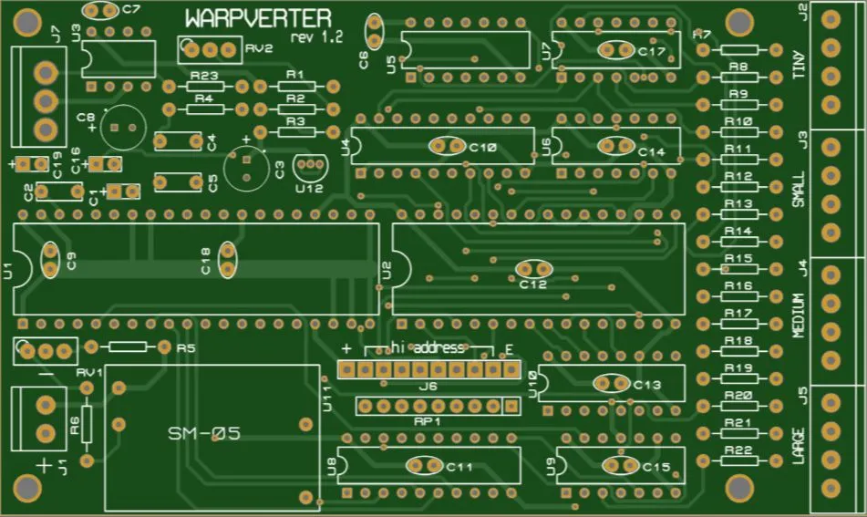
Warpverter rev 1.2 control board, bill of materials
Gerbers for ordering a circuit board are available from the downloads page.
Although not on the actual board, a suitable Hall sensor will be required.
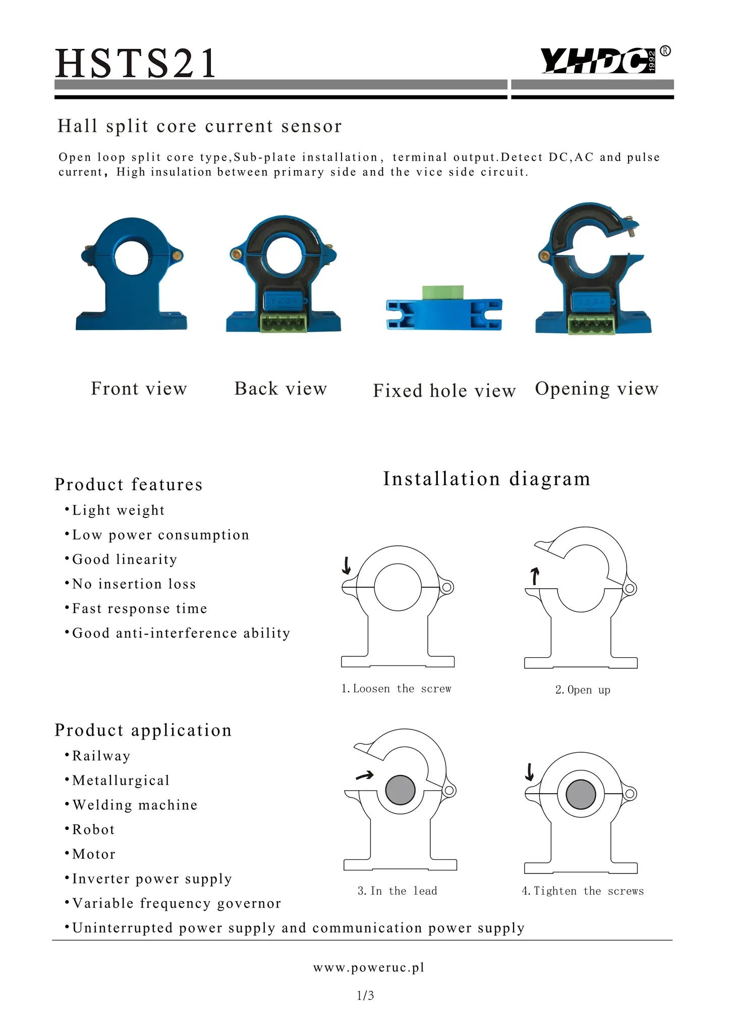
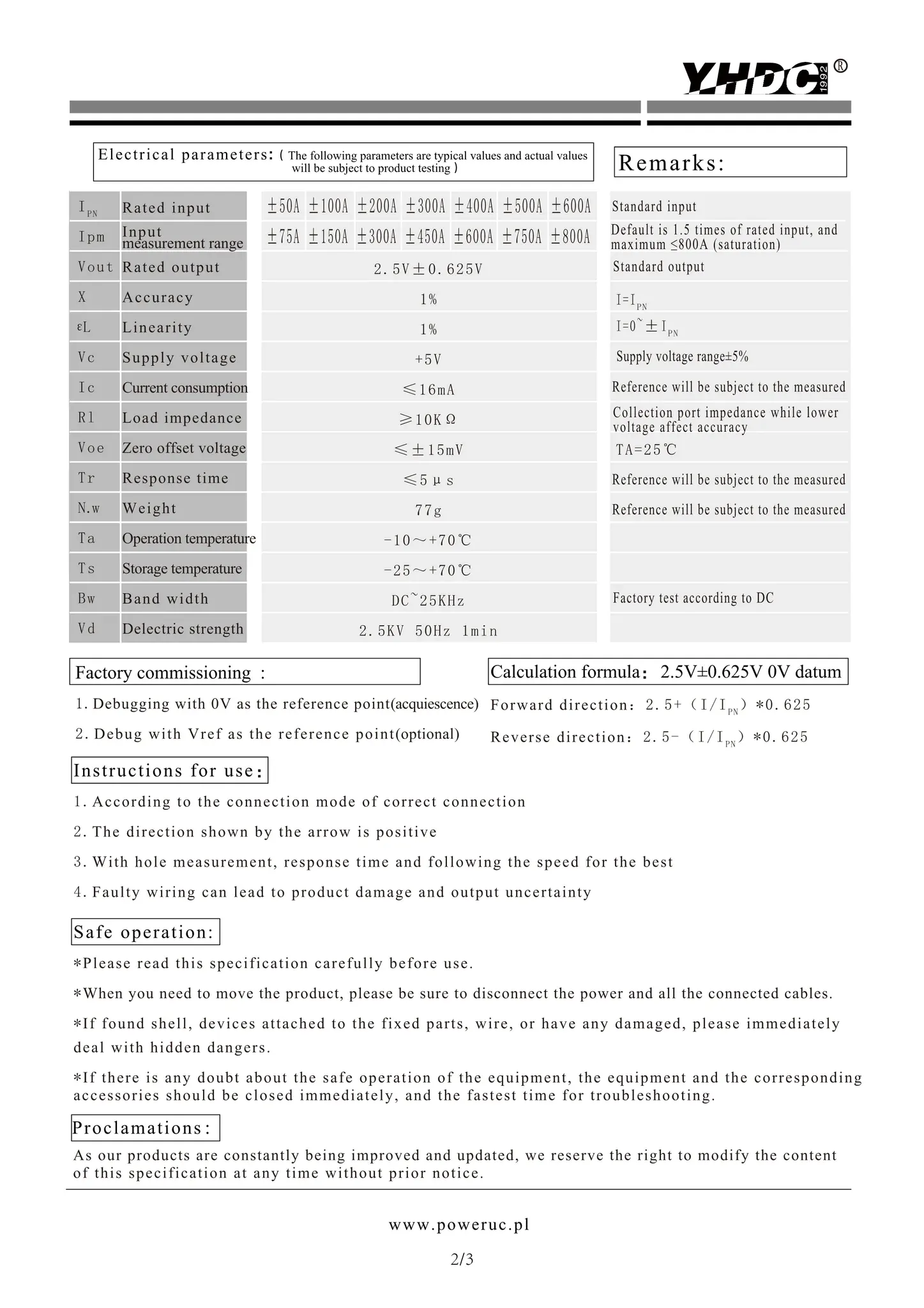
Suggested type is an HSTS21 which is available in five current ranges from +/- 100 amps to +/- 500 amps.
When powered from +5v has an output of +2.5v at zero current.
It produces a +/- 625mV output either side of +2.5v with the rated max current flow in either direction.
When deciding on a suitable current measurement range, allow for peak surge loads.
We only need a small fraction of that 625mV to correct for voltage drop in the transformer windings under heavy load. R5 and RV2 may need adjustment during final testing, although the suggested values should be a good starting point.

Click images to see full size
The HSTS21 is an ideal device, because it splits open and can be clamped around a large cable or a busbar without having to disconnect the cable.
There is also a zeroing potentiometer built into the device that can be tweaked to get the same exact 2.5v coming from the TL431 with no load on the inverter.
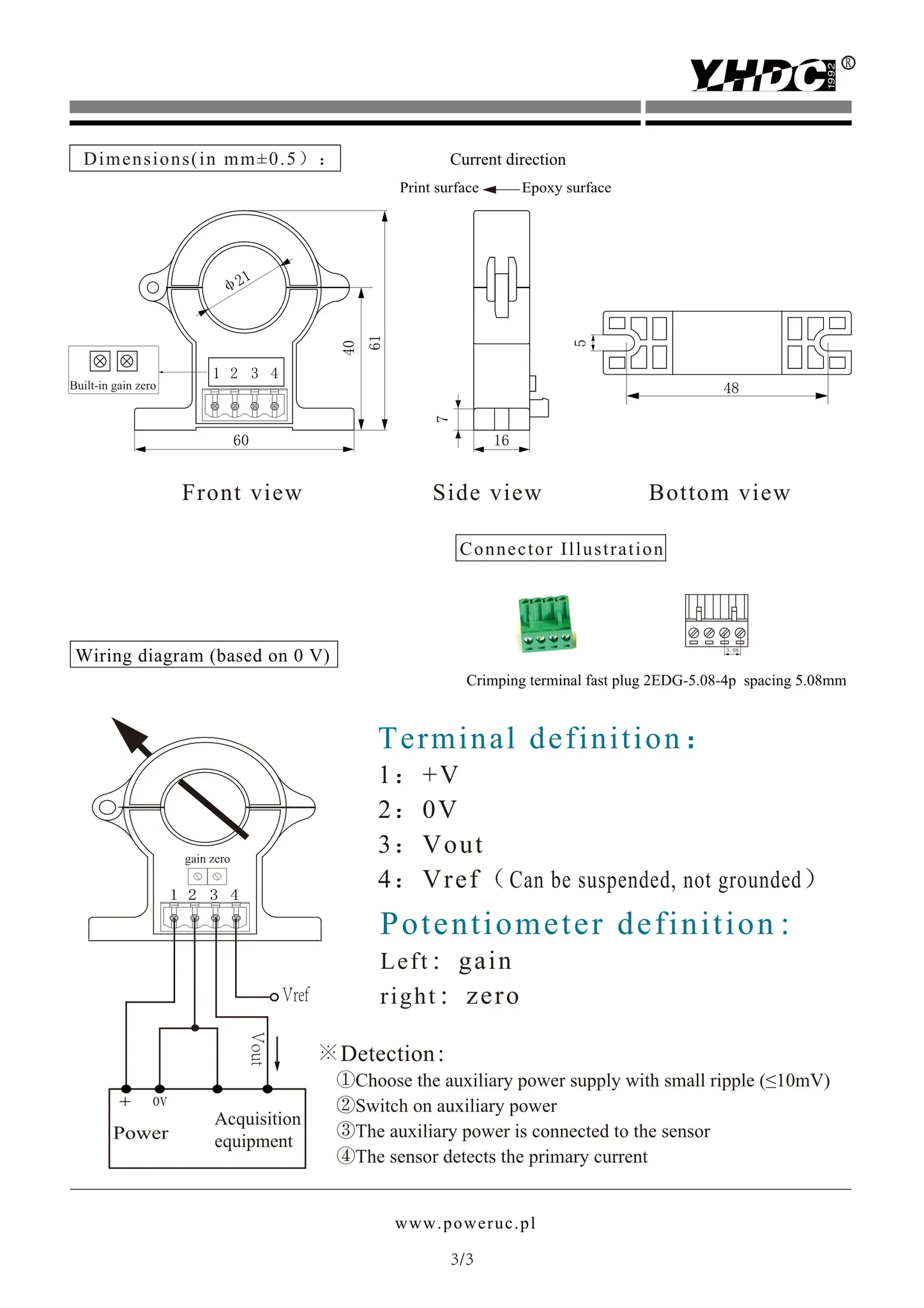
Connections between the HSTS21 and the PCB are pins 1, 2 and 3, connect to pins 1, 2 and 3.
Pin 4 on the Hall sensor is not used. A four pin plug for the HSTS21 is usually supplied with the sensor.
U11 is one of those small Chinese two dollar circuit boards used in 5v dc wall packs and readily available from e-bay or Ali.
U5 is a crystal oscillator module, metal can type, specified to work between +2v and +6v. The frequency will depend on the required inverter output frequency. 3.2768 Mhz required for 50Hz. 3.93216 Mhz for 60Hz.
There is a currently a world wide chip shortage. The 50Hz oscillators are quite readily available, but the 60Hz oscillators are out of stock everywhere.
You could use a 4.0000 Mhz oscillator, that will give you 61.035 Hz. Actual division ratio is divide down by 65,536. The 60Hz oscillators should eventually come back in stock.
61Hz should be fine for testing and even to run for a while in an off grid situation until replacements becomes possible.
Everything else is pretty straightforward.
U1 ICL7109CPL dual slope analog to digital converter
U2 W27C020 256 x 8 EEPROM. Will need to be programmed with the lookup tables.
U3 ICL7660CPA voltage pump chip
U4 74HC574N clocked eight bit latch
U5 Crystal oscillator module as above
U6 CD4024 cmos counter
U7 74HC04N hex inverter
U8 74HC574 clocked eight bit latch
U9 74HC04N hex inverter
U10 74HC4040 counter (must be HC type not an ordinary slow cmos CD4040)
U12 TL431 shunt voltage regulator
J1 Two pin right angle screw terminal block socket, pin spacing 0.15” or 3.81mm spacing.
+ Two pin straight screw terminal plug to match the above.
J2, J3, J4 and J5 Four pin right angle screw terminal block sockets. Pin spacing 0.15 “
+ Four four pin straight screw terminal plugs to match the above.
J7 Three pin right angle screw terminal block socket, pin spacing 0.15”
+ One three pin straight screw terminal plug to plug into the above.
There are straight and right angle plugs, and straight and right angle sockets.
We need the straight plugs and the right angled sockets.
One 40 pin machined contact IC socket 0.6 inches wide for U1
One 32 pin machined contact IC socket 0.6 inches wide for U2
Two 20 pin machined contact IC sockets 0.3 inches wide for U4 and U8
One 16 pin machined contact IC socket 0.3 inches wide for U10
Three 14 pin machined contact IC sockets 0.3 inches wide for U6, U7, and U9
One 8 pin machined contact IC socket 0.3 inches wide for U3
One ten pin female header strip for J6 (optional) this can be used to drive a two digit Hex display to show which lookup table is active. Not really necessary, but sometimes useful for debugging.
R1 220R metal film resistor 1%
R2 12K metal film resistor 1%
R3 47K metal film resistor 1%
R4 200K metal film resistor 1%
R5 3K3 metal film resistor 1%
R6 Determined by battery voltage range, to produce +2v to +4v output (from RV1) when RV1 is set to mid scale.
R7 to R22 (sixteen resistors) all are 180R metal film 1%
R23 10K metal film resistor 1%
RP1 In line nine pin resistor pack. Eight 4K7 resistors with a common pin.
RV1 500R potentiometer, three straight pins 0.1” pin spacing.
RV2 2K potentiometer, three straight pins 0.1” pin spacing.
C1 1uF dipped tantalum capacitor 0.1 inch lead spacing.
C2 100nF polyester rectangular plastic package 0.2 inch lead spacing.
C3 100uF electrolytic 16v 0.1 inch lead spacing.
C4 47nF polyester rectangular plastic package 0.2 inch lead spacing.
C5 100nF polyester rectangular plastic package 0.2 inch lead spacing.
C6 100nF small ceramic disc 0.1 lead spacing (oscillator module bypass).
C7 22pF ceramic disc 0.1 inch lead spacing.
C8 100uF electrolytic 16v 0.1 inch lead spacing
C9 100nF small ceramic disc 0.1 lead spacing ( located beneath U1)
C10 100nF small ceramic disc 0.1 lead spacing ( located beneath U4)
C11 100nF small ceramic disc 0.1 lead spacing ( located beneath U8)
C12 100nF small ceramic disc 0.1 lead spacing ( located beneath U2)
C13 100nF small ceramic disc 0.1 lead spacing ( located beneath U10)
C14 100nF small ceramic disc 0.1 lead spacing ( located beneath U6)
C15 100nF small ceramic disc 0.1 lead spacing ( located beneath U9)
C16 1uF dipped tantalum capacitor 0.1 inch lead spacing.
C17 100nF small ceramic disc 0.1 lead spacing ( located beneath U7)
C18 100nF small ceramic disc 0.1 lead spacing ( located beneath U1)
C19 1uF dipped tantalum capacitor 0.1 inch lead spacing.
The 100nF caps fitted underneath the IC sockets need to be quite small, but it should not be too difficult finding something.
All the components are the same for either 50Hz or 60Hz, only the oscillator module frequency changes.
Voltage ratings of capacitors are not critical. Nothing sees over five volts anyway.
Its mainly a case of finding components that fit neatly onto the board.
Download parts list and print to aid in board construction.
Control board rev 1.2 ... includes additional current feed forward (load) correction feature
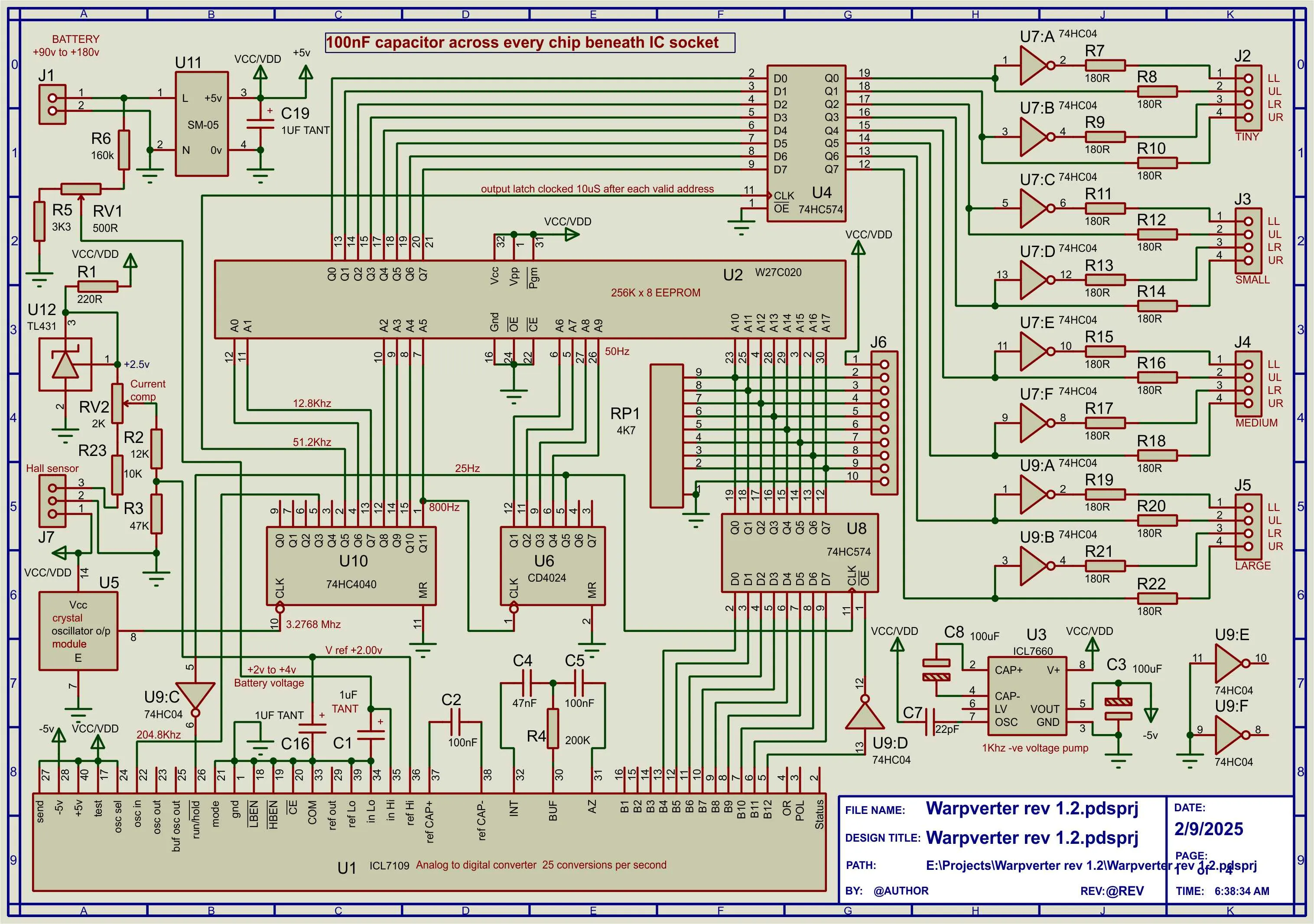
Revised version of Control board rev 1.2 ... includes extra components and socket to connect feed forward current Hall sensor
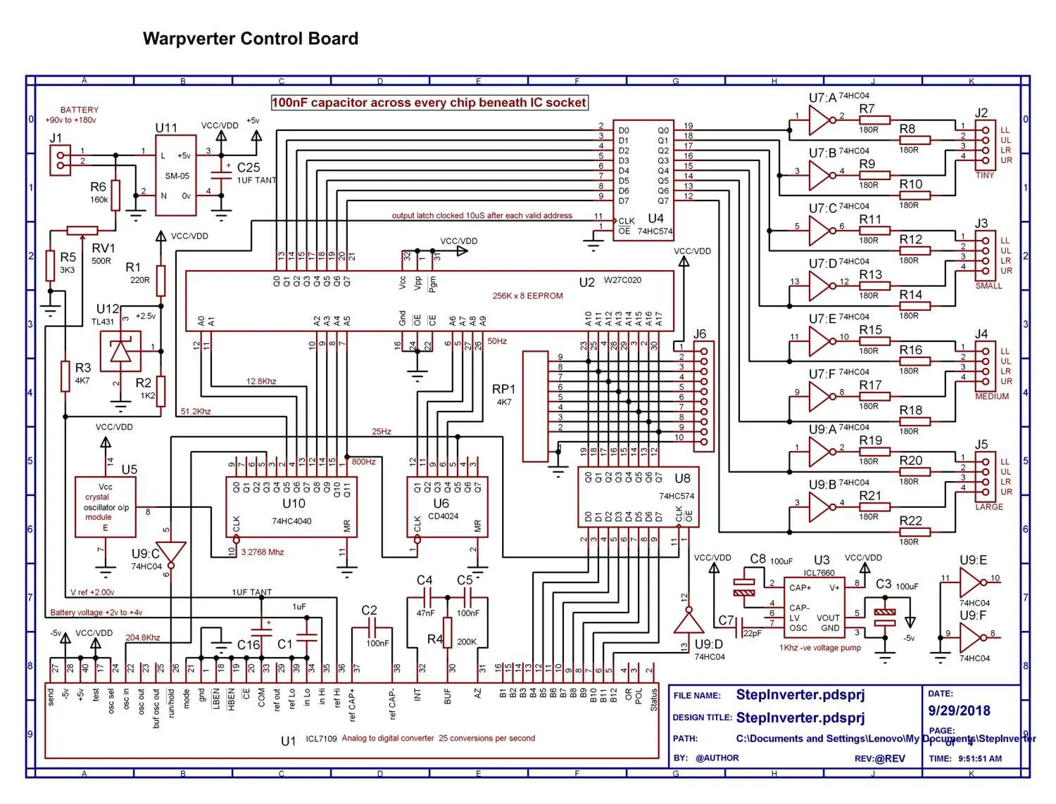
Control board ... Original circuit - rev 1.0
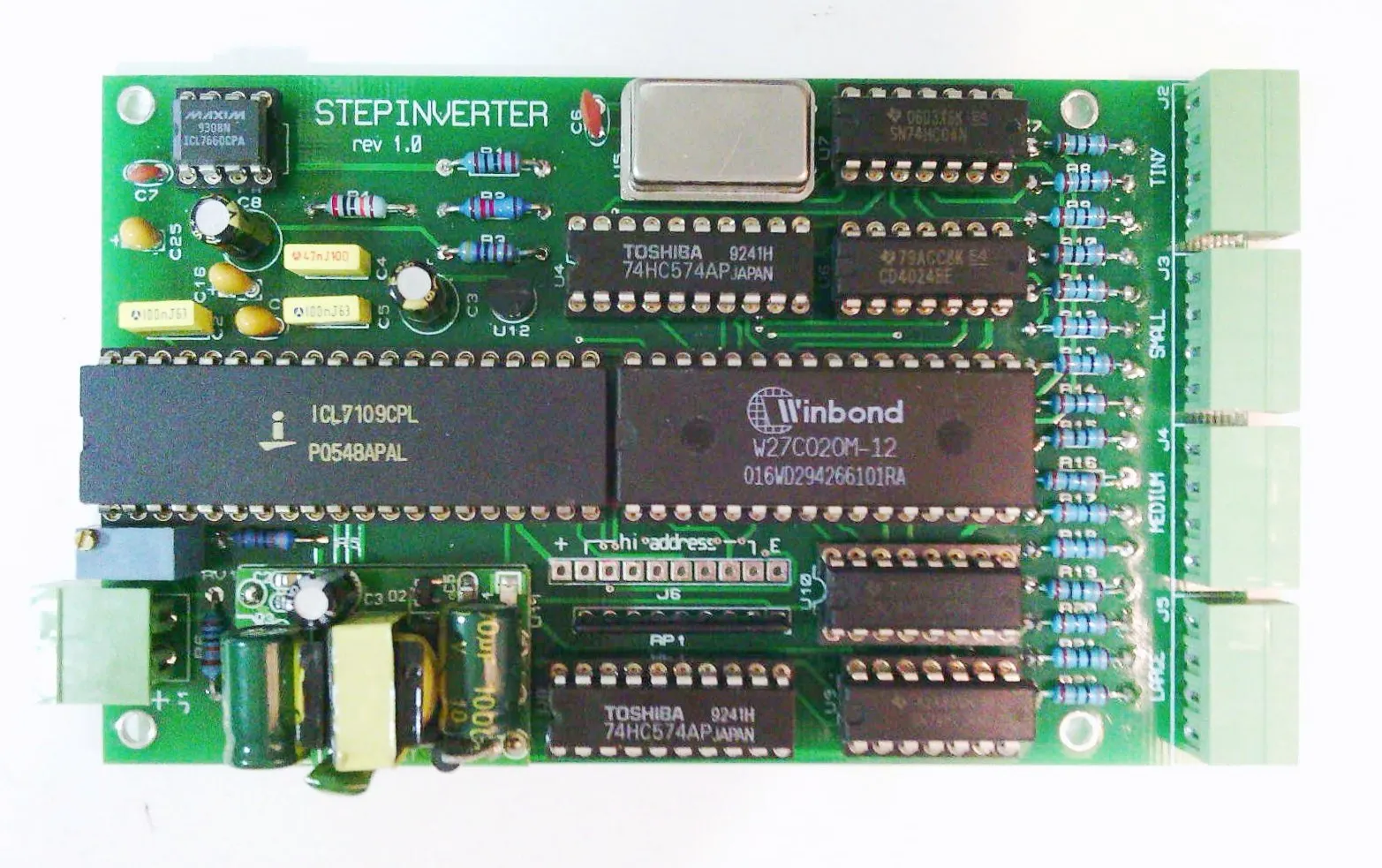
Original version of Control board rev 1.0
Click Circuits and Images to Open High Resolution Versions
Contact:Visit this thread on diysolarforum and message Warpspeed or rogerdw

© 2024 Warpverter.com - All Rights Reserved. Terms of Service: Privacy Policy:
