Warpverter
A Serious Electronic Project For The Expert DIYer
Waveforms
The theory of operation is described on the "How It Works" page ... but seeing the waveforms that make up the final output can help in understanding how it all comes together and how the output sine wave is created.
All these photos are of Tony's Warpverter's waveforms.
The top row of images is of all the individual E&I transformer secondary outputs ... with largest on the left and smallest on the right.
They are all to scale, so you can see that the larger two do most of the work ... and the smaller two just fill in the fine detail to smooth out the waveform.
The second row of three images shows the output as the individual transformers are added in series together. The image on the left shows the larger two in series ... #1 and #2
The middle image shows transformers #1, #2 and #3 in series ... and the final picture with a beautifully smooth sinewave output is with all four in series.
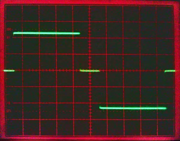
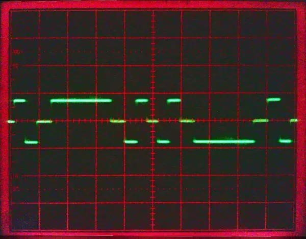
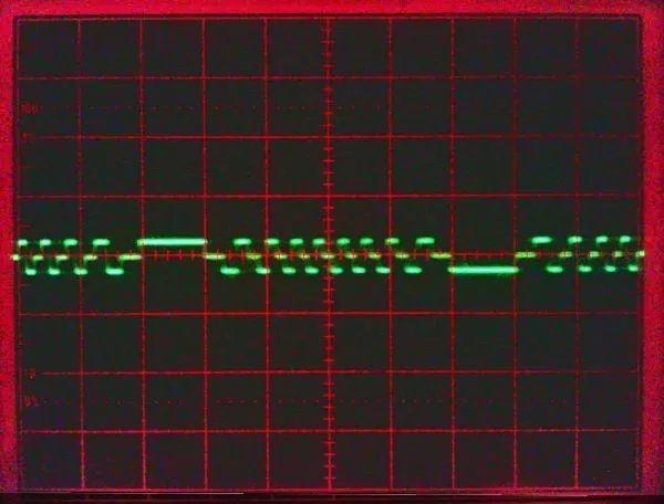
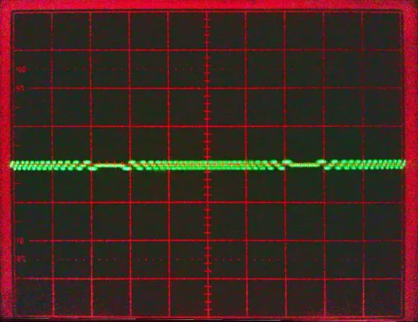
Large Transformer #1
This transformer does the bulk of the work and for a 240V inverter, is 225V P-P
MediumTransformer #2
This transformer outputs 75V P-P ... which is exactly one third the output of the #1 transformer
Small Transformer #3
The output from the small transformer is one third of #2 at 25V
Tiny Transformer #4
And the tiny transformer outputs 8.3V ... one third of #3 ... one 9th of #2 and one 27th of #1
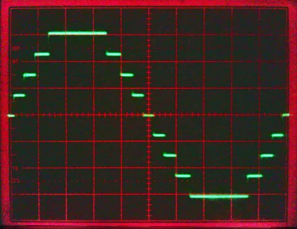
Transformers #1 + #2 in series
The result is already looking good and could probably work well enough for loads like motors and resistive loads
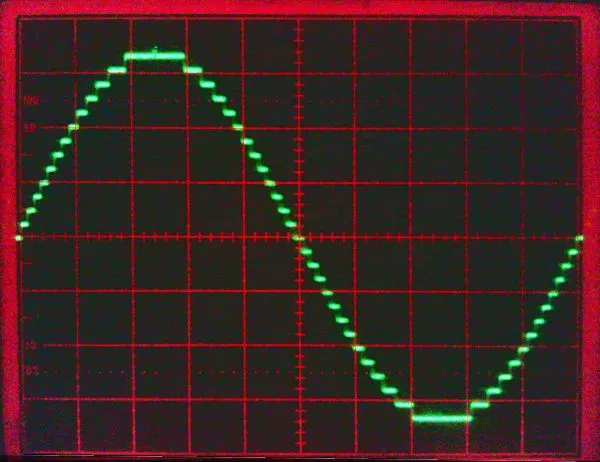
Transformers #1 + #2 + #3 in series
Looking more like a sine wave again and perfectly useable just like this. Could save a complete inverter stage. :)
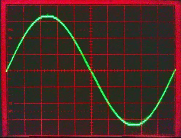
Transformers #1 + #2 + #3 + #4
Here's our final output. Would be hard to get a better looking sinewave than this.
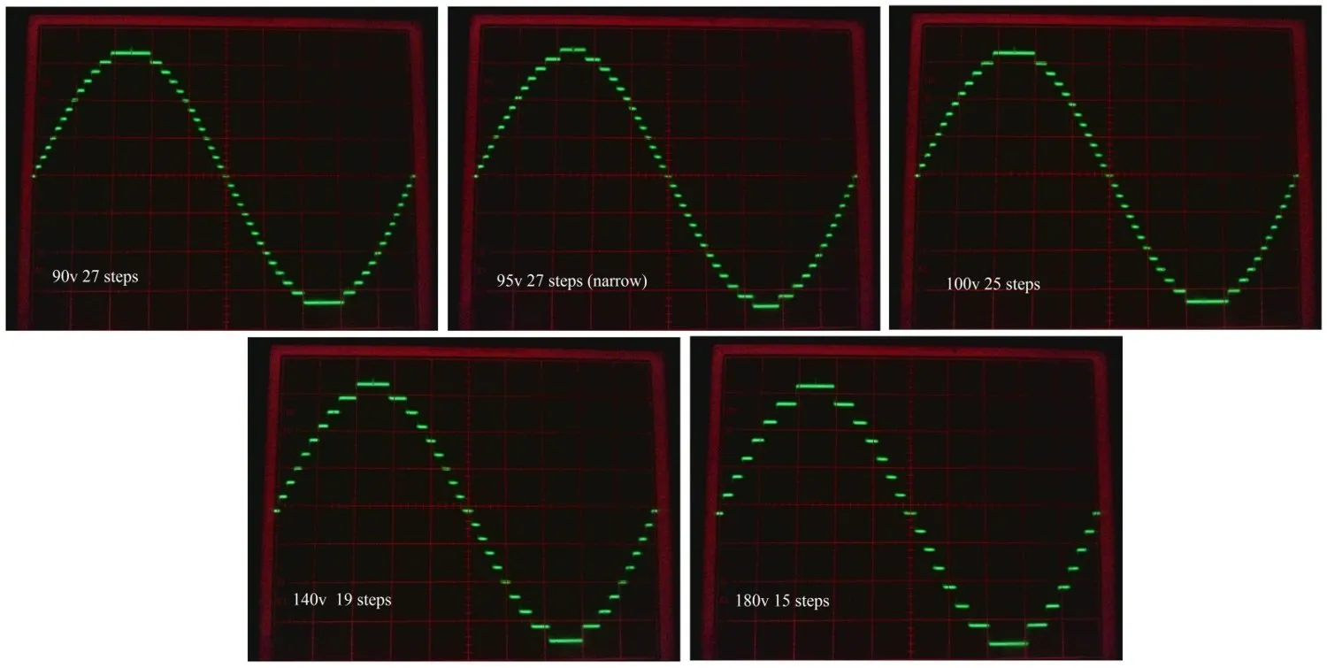
Here are some waveforms showing the effect of different DC input voltages on the AC output with only three inverters running.
The oscilloscope is set for 100v per division.
AC output voltage is held pretty constant even though the vertical height of each step increases in proportion with the increase in dc input voltage.
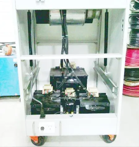
Tony's 5kW Warpverter E&I Transformers
Contact: Visit this thread on diysolarforum and message Warpspeed or rogerdw

© 2024 Warpverter.com - All Rights Reserved. Terms of Service: Privacy Policy: